
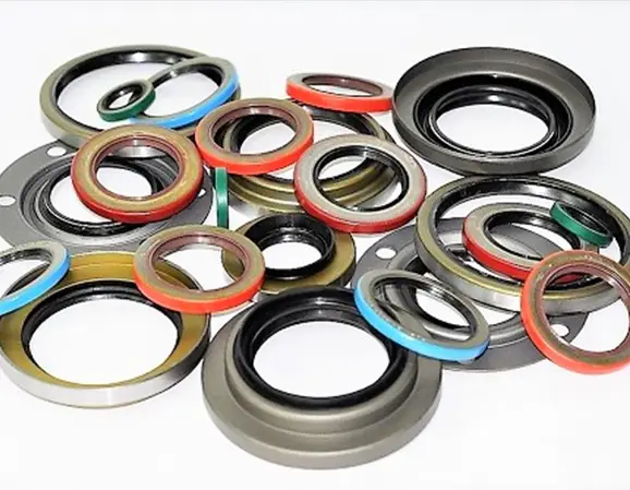
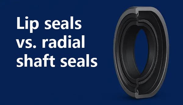
When engineers compare lip seals vs. radial shaft seals, the first challenge is terminology: in many industrial applications, the two expressions describe the same basic family of sealing technology rather than two completely different products. A radial shaft seal is commonly a rotary shaft seal that uses a sealing lip to control the passage of lubricant or contaminants between a rotating shaft and a stationary housing. In other words, a conventional radial shaft seal is a type of lip seal.
However, the phrase “lip seal” can also be used more broadly for many sealing arrangements that incorporate a flexible lip, while “radial shaft seal” normally refers specifically to a seal designed around a rotating shaft and a stationary bore. Understanding this distinction is important when selecting a seal, interpreting manufacturer catalogs, comparing materials, or diagnosing leakage.
🔧 Key engineering point: Radial shaft seals are generally lip-type seals, but not every product described informally as a “lip seal” necessarily has the same construction, pressure capability, materials, or operating limits as a standard radial shaft seal. Selection should therefore be based on shaft speed, temperature, pressure, lubricant, contamination, shaft condition, runout, housing dimensions, and required sealing direction.
What Is a Lip Seal?
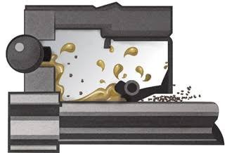
A lip seal is a sealing device that uses a flexible lip to create controlled contact against a mating surface. Depending on the application, the mating surface may be a rotating shaft, a sliding rod, a bore, or another component.
In rotary machinery, the most common form is the radial lip seal. The flexible sealing lip contacts the shaft with a controlled radial load. The seal must maintain sufficient contact to prevent unwanted fluid movement while limiting friction, heat generation, and wear.
The basic concept is deceptively simple. A flexible elastomeric lip is pressed against a rotating surface, creating a barrier between two environments. In actual operation, however, the interface is a tribological system involving elastomer deformation, lubricant film formation, friction, heat transfer, shaft surface texture, contamination, and dynamic shaft movement.
SKF describes radial shaft seals as components used between rotating and stationary machine components. Their construction commonly includes an outer case or covering that seals statically against the housing and a sealing lip made from elastomeric or thermoplastic material that seals dynamically against the shaft. A garter spring is often used to maintain radial load at the lip.
What Is a Radial Shaft Seal?
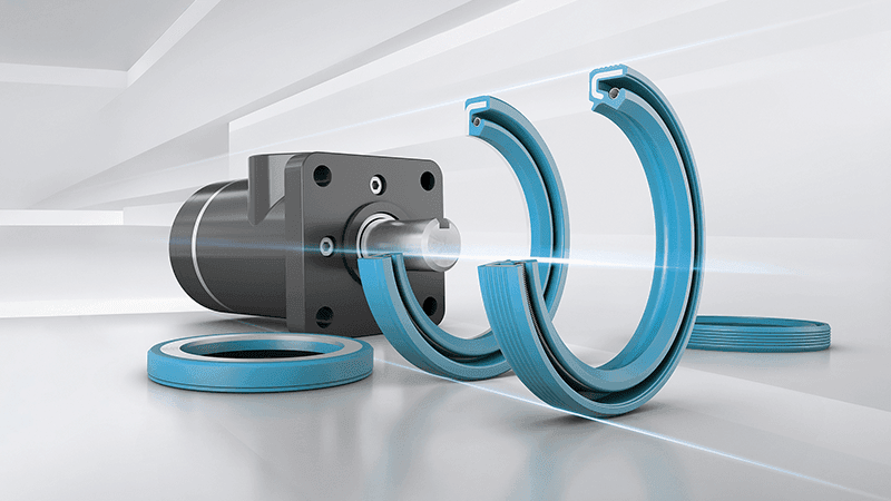
A radial shaft seal is specifically designed to seal around a shaft where the shaft rotates relative to the housing. It is commonly installed in bearings, gearboxes, transmissions, differentials, pumps, motors, agricultural machinery, construction equipment, automotive drivetrains, and industrial gear systems.
The word “radial” describes the direction in which the primary sealing force acts relative to the shaft. Instead of pressing axially against a flat face, the sealing lip applies a radial load around the shaft circumference.
A typical radial shaft seal contains several functional regions:
- Sealing lip: creates the dynamic interface with the shaft.
- Garter spring: maintains radial force in many spring-loaded designs.
- Seal case: supports the seal and provides structural stability.
- Outer diameter: provides static sealing in the housing.
- Auxiliary or dust lip: helps protect the primary lip from contamination in suitable designs.
- Hydrodynamic features: may help pump lubricant back toward the fluid side during shaft rotation.
Lip Seals vs. Radial Shaft Seals: Are They Actually Different?
The short answer is: usually not in the way people think.
In many engineering catalogs, “radial shaft seal,” “radial lip seal,” “rotary shaft seal,” and “oil seal” are used for closely related products. The exact terminology varies among manufacturers, industries, and regions.
| Term | Typical meaning | Typical application |
|---|---|---|
| Lip seal | Broad description of a seal using a flexible lip | Rotary or reciprocating sealing |
| Radial shaft seal | Rotary seal designed around a shaft | Gearboxes, motors, bearings, axles |
| Radial lip seal | Radial shaft seal emphasizing the lip mechanism | Rotating shaft applications |
| Oil seal | Application-oriented name for fluid-retaining shaft seals | Engines, transmissions, axles, gearboxes |
| Rotary shaft seal | General name for seals operating around rotating shafts | Industrial and automotive equipment |
Therefore, if a purchasing department asks for a “lip seal” and an engineer asks for a “radial shaft seal,” they may be referring to essentially the same product. The critical issue is not the label but the engineering specification.
How a Radial Lip Seal Actually Seals
A common misconception is that a lip seal works simply by creating a perfectly dry, high-pressure contact between rubber and metal. In reality, the sealing interface depends on controlled contact pressure and lubrication.
The lip is intentionally deformed against the shaft. A combination of elastomer elasticity and, where present, garter-spring force creates radial loading. During rotation, a microscopic lubricant film can develop between the lip and shaft.
The seal must maintain enough contact to restrict bulk fluid leakage while avoiding excessive friction that would generate unnecessary heat.
⚙️ Tribology principle: A successful dynamic seal does not necessarily mean “zero lubricant at the lip.” A controlled microscopic lubricant film can reduce direct solid-to-solid contact, lowering friction and wear while the seal geometry controls fluid migration.
The Difference Between Static and Dynamic Sealing
Understanding static versus dynamic sealing is essential when comparing seal designs.
A static seal operates between surfaces that do not move relative to each other. An O-ring compressed in a stationary groove is a common example.
A dynamic radial shaft seal operates while the shaft rotates relative to the seal. This introduces friction, heat, wear, lubrication-film behavior, shaft surface requirements, and speed limitations.
| Characteristic | Static seal | Radial shaft lip seal |
|---|---|---|
| Relative movement | None or negligible | Continuous shaft rotation |
| Friction | Usually very low after installation | Continuous dynamic friction |
| Heat generation | Generally low | Can be significant at high speed |
| Shaft finish | Less critical in many designs | Critical |
| Wear | Usually minimal | Expected and must be controlled |
Primary Lip vs. Auxiliary Lip
Many radial shaft seals have more than one lip. The primary lip performs the main fluid-retention function, while a secondary lip may protect the primary lip from external contamination.
A typical double-lip arrangement may therefore have an oil-side primary lip and an air-side dust or exclusion lip.
The auxiliary lip is not automatically an improvement in every application. A contacting auxiliary lip creates additional friction and heat. SKF notes that auxiliary lips can improve contamination protection but may also increase friction and under-lip temperature. Non-contacting auxiliary designs can provide contamination protection with less additional friction.
Spring-Loaded vs. Non-Spring-Loaded Lip Seals
A garter spring is commonly used in oil-retention applications because it maintains radial force as the elastomer experiences dimensional changes during operation and aging.
Non-spring-loaded lips can be suitable for certain grease applications or lower-demand conditions. SKF indicates that grease is generally easier to retain than oil because of its higher viscosity, while more demanding applications may require spring-loaded radial shaft seals.
This distinction is important because “lip seal” does not tell you whether the seal contains a spring. Two products with identical nominal dimensions may have different performance characteristics because their lip designs differ.
When Should You Choose a Radial Shaft Seal?
Radial shaft seals are particularly appropriate when a rotating shaft must pass through a stationary housing while lubricant must be retained and external contamination controlled.
Typical applications include:
- Electric motors
- Industrial gearboxes
- Automotive transmissions
- Differentials and axles
- Wheel hubs
- Agricultural machinery
- Construction equipment
- Pumps
- Hydraulic and mechanical drives
- Power take-off systems
- Bearings and bearing housings
- Conveyor drives
SKF identifies applications including transmissions, differentials, transfer cases, and power take-off units, with radial lip shaft seals used at input, output, pump, and shifter shafts.
When a Standard Radial Lip Seal Is Not the Best Choice
A contacting radial lip seal is not automatically the best solution for every rotating shaft.
At extremely high speeds, the friction generated by a contacting lip can become a major design limitation. Non-contacting labyrinth or gap seals may be preferable where contamination and fluid requirements permit.
SKF has described radial lip seals as effective contamination barriers but also notes that their friction and resulting heat can limit speed. In one SKF technical reference, radial lip seals are described as typically having allowable peripheral speeds around 7–8 m/s, although actual limits vary substantially with seal design, material, lubrication, shaft diameter, temperature, and application.
This is why high-speed machinery may use labyrinth seals, mechanical face seals, PTFE-based designs, or other specialized technologies rather than a conventional elastomeric lip.
Lip Seal vs. Labyrinth Seal
| Feature | Radial lip seal | Labyrinth seal |
|---|---|---|
| Contacting | Yes | Normally non-contacting |
| Friction | Higher | Very low |
| Oil retention | Generally strong | Application dependent |
| Contamination exclusion | Good with appropriate design | Good in suitable environments |
| High-speed suitability | Application dependent | Generally excellent |
| Wear mechanism | Lip/counterface wear | Minimal contact wear |
The choice depends on whether the application prioritizes positive fluid retention, contamination exclusion, high speed, low friction, or a combination of requirements.
Material Selection: NBR, FKM, ACM and PTFE
Material selection is one of the most important differences between apparently similar lip seals.
NBR
Nitrile rubber is widely used for oil seals because of its balance of oil resistance, mechanical properties, abrasion resistance, cost, and manufacturing flexibility. It is often suitable for mineral-oil-based lubricants within the compound’s specified temperature range.
FKM
Fluoroelastomer compounds can provide excellent resistance to elevated temperatures and many aggressive fluids. They are frequently considered when conventional NBR compounds approach their temperature or chemical limits.
ACM
Polyacrylate elastomers are used in selected automotive applications where high-temperature resistance and compatibility with particular lubricants are important.
PTFE
PTFE sealing elements are used in applications requiring low friction, chemical resistance, or higher temperature capability. PTFE lip designs may require different installation methods and shaft surface requirements compared with conventional elastomeric seals.
SKF offers radial shaft seal designs using both elastomeric and PTFE sealing elements for demanding conditions including aggressive lubricants, high contamination, wide temperature ranges, and significant misalignment.
Hardness and Lip Performance
Elastomer hardness is commonly expressed using Shore A hardness for rubber compounds. However, hardness alone does not determine seal performance.
A seal compound’s modulus, elongation, compression set, tensile strength, abrasion resistance, low-temperature flexibility, fluid swelling, thermal aging, and friction characteristics can all influence performance.
For example, increasing hardness can improve resistance to deformation in some situations, but an excessively stiff lip may not accommodate shaft eccentricity or surface irregularities as effectively as a properly formulated flexible lip.
Expert tip: Never specify a radial shaft seal simply as “90 Shore rubber.” Specify the complete material compound, seal geometry, dimensional standard, temperature range, fluid compatibility, speed requirement, and environmental conditions.
Shaft Surface Finish Is Critical
The shaft is effectively the counterface for the sealing lip. Its surface finish can determine whether the seal operates with controlled lubrication or excessive wear.
ISO 6194-1:2007 specifies dimensional and tolerance requirements for rotary shaft lip-type seals incorporating elastomeric sealing elements. It includes guidance for shaft and housing geometry, including shaft diameter tolerance and counterface surface requirements. The standard identifies a typical ground-shaft contact roughness range of Ra 0.2–0.5 μm for the specified configuration, with shaft hardness requirements that can increase under handling or damage risks.
These values should not be copied blindly into every application. Seal manufacturers may specify different requirements based on seal material, lip design, speed, lubricant, and service conditions.
Why Surface Roughness Is a Tribological Issue
A shaft surface that is too rough can act as an abrasive counterface. Peaks in the surface can penetrate or disturb the lubricant film, increasing friction and wear.
But an extremely smooth surface is not automatically ideal either. The sealing interface depends on controlled lubricant retention and microscopic surface interactions.
The goal is therefore not simply “the smoothest possible shaft.” The goal is a surface with the appropriate texture, directionality, hardness, and geometry for the selected seal.
Speed and Surface Velocity
Seal designers often evaluate circumferential speed rather than shaft rpm alone because a larger shaft produces higher sliding velocity at the same rotational speed.
v = πDN / 60
v = circumferential speed in m/s
D = shaft diameter in meters
N = rotational speed in rpm
For an illustrative 50 mm shaft rotating at 3,000 rpm:
v = π × 0.050 × 3,000 / 60 ≈ 7.85 m/s.
This simple calculation demonstrates why a seal that is acceptable at 1,000 rpm may become thermally challenging at 3,000 rpm. The calculation is an engineering example and is not a claim of a universal allowable speed for a particular seal.
Friction and Heat Generation
Every contacting lip seal generates some friction. A simplified relationship for frictional power is:
P ≈ F × v
where P is frictional power, F is effective friction force, and v is sliding velocity.
As speed increases, sliding velocity increases. If friction force remains similar, frictional power also increases. In real seals, however, friction is not constant: it changes with temperature, lubrication, lip design, material, pressure, shaft surface, and speed.
SKF testing of conventional and hydrodynamically optimized radial lip designs demonstrates that lip geometry can materially influence friction and temperature. SKF reports that its Wave seal design can reduce friction by up to 20% and temperature by up to 30% under the referenced test conditions. These are manufacturer test results for that particular design and test setup, not universal performance values for every lip seal.
Hydrodynamic Lip Designs
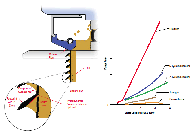
Some radial shaft seals incorporate grooves, waves, ribs, or other features into the sealing edge. These features can generate a pumping effect that helps return lubricant toward the fluid side of the seal.
This is especially useful where oil retention is important and the shaft rotates continuously.
The direction of rotation can matter for certain hydrodynamic designs. SKF notes that some spiral features are designed for clockwise or counter-clockwise shaft rotation, while certain Wave-type designs are suitable for both directions.
⚠️ Selection warning: Do not assume that every lip seal is suitable for bidirectional rotation. Check the manufacturer’s design and rotation requirements, especially when the lip incorporates directional hydrodynamic features.
Pressure Capability: An Often-Misunderstood Issue
Standard radial shaft seals are primarily designed for relatively low pressure differentials. They should not automatically be treated as substitutes for hydraulic pressure seals.
ISO 6194-1 describes the standard class as intended for low-pressure conditions and specifies typical use with pressure from 0 to 30 kPa above atmospheric pressure, while recommending consultation with the manufacturer for other pressure conditions.
30 kPa is approximately 0.3 bar or 4.35 psi.
This distinction is important. A gearbox shaft seal that is perfectly suitable for retaining oil in a low-pressure housing may be completely unsuitable for a hydraulic cylinder operating at hundreds or thousands of psi.
Case Example: Two Seals With the Same Dimensions
Case Example — illustrative engineering scenario, not a real customer case:
Imagine two seals with the same nominal shaft diameter, housing diameter, and width. Seal A uses a conventional NBR spring-loaded lip. Seal B uses a high-temperature FKM compound and a low-friction lip geometry.
An engineer might incorrectly conclude that the two seals are interchangeable because their dimensions match.
Now consider an application with continuous operation at high shaft speed, elevated lubricant temperature, and a chemically aggressive synthetic lubricant. Seal A may experience accelerated aging or friction-related temperature rise while Seal B may be better suited to the environment.
The example illustrates an important principle: dimensional interchangeability does not necessarily mean functional interchangeability.
Laboratory Test Example
Laboratory Test Example — illustrative methodology only; no customer test data or fabricated service-life curve is being claimed:
A laboratory comparing two radial shaft seal designs could use a controlled rotating shaft rig. The objective would be to isolate the effect of seal design while controlling other variables.
| Parameter | Example laboratory control |
|---|---|
| Shaft diameter | Fixed representative diameter |
| Speed | Multiple controlled rpm levels |
| Lubricant | Specified production fluid |
| Temperature | Controlled housing or sump temperature |
| Runout | Controlled shaft eccentricity |
| Measurements | Torque, temperature, leakage, wear, shaft track |
ISO 6194-4 provides general performance test procedures for rotary shaft lip-type seals. A properly controlled test can help compare seal designs, identify failure mechanisms, and establish application-specific qualification criteria.
However, a laboratory test should not be converted directly into a mileage guarantee. Field conditions introduce variables such as contamination, thermal cycling, shaft misalignment, lubricant degradation, vibration, and installation variation.
Failure Mode Analysis of Lip and Radial Shaft Seals
Failure Mode 1: Lip Wear
Wear occurs at the moving contact interface. Excessive wear may be caused by poor lubrication, high temperature, high speed, contaminated lubricant, inappropriate shaft finish, excessive radial load, or material incompatibility.
Failure Mode 2: Shaft Groove
A shaft may develop a circumferential wear groove where the lip contacts it. Installing another seal in exactly the same position may produce another leakage path.
Failure Mode 3: Lip Hardening
Thermal aging and chemical exposure can change elastomer properties. A hardened lip may lose its ability to accommodate shaft movement and maintain the intended contact pressure.
Failure Mode 4: Lip Cracking
Cracking can occur because of thermal degradation, incompatible fluids, ozone exposure for susceptible compounds, improper storage, or mechanical damage.
Failure Mode 5: Contamination Damage
Dust, sand, metal particles, or other contaminants can become trapped near the lip and produce abrasive wear.
Failure Mode 6: Leakage From Installation Damage
The lip can be cut or distorted during installation, especially when it passes over splines, keyways, threads, burrs, or sharp shaft shoulders.
Failure Mode 7: Excessive Pressure
Pressure above the seal’s intended design range can distort the lip, increase friction, and promote leakage.
Installation Requirements for Radial Shaft Seals
Correct installation is one of the most important factors in seal reliability.
- Clean the housing bore and shaft.
- Inspect the shaft for grooves, corrosion, burrs, and machining damage.
- Verify the correct seal dimensions and material.
- Confirm the correct sealing direction.
- Protect the lip from sharp edges and splines.
- Lubricate the lip with a compatible lubricant where specified.
- Use a proper installation tool.
- Keep the seal square to the housing bore.
- Seat the seal to the specified installation depth.
- Confirm that the spring remains correctly positioned.
- Inspect the assembly before starting the machine.
SKF identifies improper installation as a common cause of premature seal failure and emphasizes cleanliness, proper lip lubrication, and correct seating during installation.
Why the Seal Installation Direction Matters
For a conventional oil-retention seal, the primary lip generally faces the fluid side. The spring is normally located on the fluid side of the primary lip.
However, the correct orientation depends on the actual seal design and application. Some seals are intended primarily for contamination exclusion, while others are designed for fluid retention or pressure control.
SKF notes that radial shaft seals are most effective at retaining material in the direction toward which the lip is facing and that contamination-exclusion requirements can influence lip orientation.
How to Choose Between Single-Lip and Double-Lip Designs
| Design | Advantages | Considerations |
|---|---|---|
| Single primary lip | Lower friction, simpler design | Less protection from external contamination |
| Primary + contacting dust lip | Improved contamination exclusion | Additional friction and heat |
| Primary + non-contacting exclusion feature | Contamination protection with lower additional friction | Application-specific performance |
Lip Seals and Corrosion Resistance
Seal material is only part of corrosion resistance. The shaft, spring, case, lubricant, and external environment must also be considered.
For example, an elastomer may have good chemical resistance while an exposed carbon-steel spring is vulnerable to corrosion in a wet environment. Stainless or specially protected components may therefore be required for particular applications.
Water contamination can also affect the lubricant and the shaft surface. Corrosion pits on the shaft can subsequently damage the lip.
Temperature and Thermal Conductivity
Thermal management is important because frictional heat is generated at the lip-to-shaft interface.
Elastomers generally have much lower thermal conductivity than metals. This means heat generated at a small contact zone may not dissipate in exactly the same manner as heat generated in the steel shaft or housing.
The actual thermal balance depends on shaft material, housing material, lubricant, seal geometry, rotational speed, contact pressure, ambient temperature, and heat transfer paths.
For this reason, using a material simply because it has a high published maximum temperature can be misleading. The actual lip temperature may differ significantly from the bulk lubricant temperature.
Pressure, Speed and Temperature Must Be Evaluated Together
Seal selection should not treat speed, temperature, and pressure as independent variables. Increasing speed increases sliding velocity. Increasing friction increases heat. Higher temperature can alter elastomer modulus and lubricant viscosity. Pressure can increase lip deformation and friction.
The combined effect can be nonlinear.
Engineering principle: A seal that performs successfully at 2,000 rpm and 80°C cannot automatically be assumed to perform equally at 5,000 rpm and 120°C simply because the seal material’s published temperature limit appears higher than 120°C.
Common Applications of Radial Shaft Seals
Radial shaft seals are used throughout mechanical engineering because they provide a practical solution for rotating shafts that must retain fluids or exclude contaminants.
Automotive
Applications include crankshafts, camshafts, transmissions, differentials, axle shafts, wheel hubs, transfer cases, and other rotating components.
Industrial Gearboxes
Gearboxes frequently require seals at input and output shafts to retain oil and prevent contamination.
Agricultural Equipment
Tractors, combines, irrigation systems, harvesters, and other agricultural machines can require seals that tolerate dust, soil, moisture, temperature changes, and shock loading.
Pumps and Motors
Rotating shafts in pumps and electric motors often use radial seals to protect bearings and retain lubricants.
A Practical Selection Guide
| Question | Why it matters |
|---|---|
| What is the shaft diameter? | Determines seal size and lip geometry |
| What is the shaft speed? | Determines sliding velocity and frictional heat |
| What is the operating temperature? | Controls elastomer and lubricant performance |
| What fluid is being sealed? | Determines chemical compatibility |
| Is there pressure? | Determines whether a standard radial seal is suitable |
| Is contamination severe? | May require an auxiliary exclusion lip |
| Is shaft runout significant? | May require a high-flex seal design |
| What is the shaft finish? | Controls wear and lubrication-film behavior |
Case Example: Same Size, Different Performance
Case Example — illustrative industry scenario:
An industrial gearbox requires a 60 mm shaft seal. Two suppliers offer products with identical nominal dimensions. Supplier A provides a conventional NBR seal with a standard spring-loaded lip. Supplier B provides a low-friction design using a modified lip geometry and a different elastomer compound.
The machine operates continuously at elevated speed and temperature.
If purchasing evaluates only the 60 × housing-bore × width dimensions, the products appear interchangeable. If engineering evaluates shaft velocity, lubricant, temperature, contamination, lip friction, and material compatibility, the difference becomes significant.
The lesson is that seal dimensions define whether a component can physically fit; they do not define whether it will perform reliably.
Failure Analysis: Leakage Immediately After Installation
If leakage begins immediately after installation, consider installation-related causes first.
- Lip cut during installation
- Seal installed backward
- Seal cocked in the housing
- Incorrect seal dimensions
- Seal lip installed dry
- Garter spring displaced
- Sharp shaft edge damaged the lip
- Contamination introduced during assembly
- Incorrect installation depth
Early leakage is not necessarily evidence that the elastomer compound is unsuitable.
Failure Analysis: Leakage After Long Service
When a seal operates successfully for a long period and then begins leaking, likely mechanisms include normal lip wear, shaft groove formation, elastomer aging, lubricant degradation, increased shaft runout, bearing wear, or environmental contamination.
The removed seal should be examined carefully. The wear pattern can reveal whether the lip contacted the shaft uniformly or whether a particular section experienced excessive wear.
How to Inspect a Failed Radial Shaft Seal
A useful failure-analysis inspection should include both the seal and the machine.
- Photograph the seal before cleaning.
- Identify the fluid side and air side.
- Inspect the primary lip for wear.
- Inspect the spring position.
- Look for hardening or cracking.
- Look for abrasive particles.
- Inspect the shaft contact track.
- Check shaft roughness and groove depth where appropriate.
- Check shaft runout.
- Inspect the housing bore.
- Verify lubricant compatibility.
- Review operating temperature and speed.
Standards and Engineering References
ISO 6194 is one of the key standards families for rotary shaft lip-type seals. ISO 6194-1 covers nominal dimensions and tolerances for seals incorporating elastomeric sealing elements, while the series also addresses vocabulary, storage and installation, and performance testing. ISO 16589 covers rotary shaft lip-type seals incorporating thermoplastic sealing elements.
Standards should be used as engineering references rather than as substitutes for the manufacturer’s application-specific recommendations. A seal that meets a dimensional standard can still be unsuitable for a particular lubricant, speed, temperature, pressure, or contamination level.
Frequently Asked Questions
FAQ 1: Are lip seals and radial shaft seals the same thing?
In many industrial contexts, yes. A conventional radial shaft seal is a type of lip seal designed to seal around a rotating shaft. However, “lip seal” is a broader informal term, so the exact construction should always be confirmed from the manufacturer’s specification.
FAQ 2: What is the difference between an oil seal and a radial shaft seal?
They often describe essentially the same family of products. “Oil seal” emphasizes the fluid-retention application, while “radial shaft seal” describes the mechanical sealing arrangement around a rotating shaft.
FAQ 3: Is a double-lip seal always better than a single-lip seal?
No. A second contacting lip can improve contamination exclusion, but it also adds friction and heat. In clean environments or high-speed applications, a lower-friction single-lip design may be preferable. The correct choice depends on the application.
FAQ 4: Can a radial shaft seal handle high pressure?
Standard radial shaft seals are generally intended for low-pressure applications. ISO 6194-1 describes the standard type for low-pressure service and identifies a typical range up to 30 kPa above atmospheric pressure. Higher-pressure applications require a seal specifically designed and qualified for that pressure.
FAQ 5: What is the most important factor when choosing a radial shaft seal?
There is no single factor that always dominates. Temperature, speed, pressure, lubricant, shaft condition, runout, contamination, orientation, and required service life must be evaluated together. The best seal is the one whose material and geometry are matched to the complete operating environment rather than simply the one with the lowest purchase price or the same nominal dimensions.
Final Engineering Perspective
The comparison between radial seals and lip seals becomes much clearer once terminology is separated from engineering function. In most rotary machinery applications, a radial shaft seal is itself a lip-type sealing solution.
The real engineering decision is therefore not simply “lip seal or radial shaft seal?” It is whether the selected radial sealing design can reliably manage the actual combination of shaft speed, surface velocity, temperature, pressure, lubricant, contamination, shaft finish, runout, alignment, and installation conditions.
A conventional spring-loaded elastomeric lip may be an excellent solution for a gearbox or differential. A hydrodynamic lip may be preferable when oil retention and friction reduction are important. A double-lip configuration may be appropriate in contaminated environments. A PTFE-based design may be selected for demanding chemical or temperature conditions. A labyrinth seal may be preferable when very high speed and minimal friction are more important than positive fluid retention.
🔍 Final expert conclusion: Do not choose a seal from the name alone. “Lip seal,” “radial shaft seal,” “rotary shaft seal,” and “oil seal” can describe closely related technologies, but performance depends on the detailed design. The most reliable selection process begins with the application conditions and ends with verification of dimensions, material, lip geometry, shaft counterface, installation method, and operating limits.