
O-groove design
O-groove design overview
KODA has developed a guide to O-ring groove design and gland dimensional specifications, aiming to provide engineers with basic design references and help them master the core principles of O-ring gland and groove design. The rational design of glands and grooves requires comprehensive consideration of multiple factors, including but not limited to the type of sealing condition (static/dynamic), system pressure conditions, characteristics of the sealed medium, and tolerance matching requirements between the O-ring and the gland.
Find the appropriate O-ring cross section
The cross-sectional dimensions of O-rings are a core baseline parameter in the design process, directly determining the setting of all subsequent related dimensions and specifications.
Standard O-rings offer a wide range of cross-sectional dimensions and inner diameter (ID) combinations. For example, according to the AS568 standard, an O-ring with an inner diameter of 5 ¼ inches is available in four compliant cross-sectional size options.
Technical advantages of small cross-section O-rings
- If your design requires the use of higher-priced elastomers like FKM or FFKM, this type of O-ring offers the best value.
- Furthermore, its smaller size simplifies the machining of the corresponding sealing groove, reducing the number of processing steps.
Technical advantages of large cross-section O-rings
A sealing effect can be achieved with lower extrusion pressure, reducing the problem of permanent deformation of O-rings due to prolonged compression that prevents them from springing back.
Furthermore, while ensuring uncompromised sealing performance, the machining tolerances for the grooves can be relaxed, simplifying the manufacturing process.
ID/OD interference
When designing O-rings, the inner or outer diameter should be determined according to the following rules to ensure appropriate tightness (interference) after installation:
Piston seal: The inner diameter of the O-ring is slightly smaller than the outer diameter of the piston. After installation, tighten it slightly, with a maximum stretch of 5%.
Piston rod gland seal: The outer diameter of the O-ring is slightly larger than the inner diameter of the gland, with a dimensional difference exceeding 2%.
External pressure face seal: The inner diameter of the O-ring is slightly smaller than the inner diameter of the gland, with a maximum dimensional difference not exceeding 5%.
Internal pressure face seal: The outer diameter of the O-ring is slightly larger than the outer diameter of the gland, with a dimensional difference controlled within 3%.
O-ring groove/sealing ring type
The following are four standard application groove design guidelines and corresponding dimensional reference diagrams, applicable to industrial end face or flange sealing conditions; applicable to static industrial radial sealing scenarios; applicable to dynamic industrial reciprocating motion sealing needs; and applicable to dovetail groove sealing structure design.
The above O-ring groove design guidelines can provide standardized dimensional references for the design of various basic sealing groove types.
Flange/Face Seal
Flange/face seals are static sealing structures with tight, gapless sealing surfaces, which can fundamentally avoid design risks related to O-ring extrusion and deformation, and represent the simplest sealing groove design.
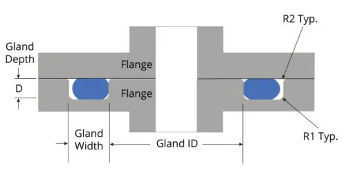
| AS568 Series | O-Ring Cross-Section | Gland Depth (D) | Squeeze | Gland Width (W) Liquids | Gland Width (W) Vacuum & Gases | Gland Corner Radii | |||||
|---|---|---|---|---|---|---|---|---|---|---|---|
| Nominal | TOL (+/-) | Actual | Percent | Nominal | TOL (+/-) | Nominal | TOL (+/-) | R1 | R2 | ||
| -0XX | 0.070 | 0.003 | .055-0.057 | .010-.018 | 15%-25% | 0.103 | 0.002 | 0.084 | 0.003 | 0.010 | 0.005 |
| -1XX | 0.103 | 0.004 | .088-.090 | .010-.018 | 10%-17% | 0.140 | 0.003 | 0.121 | 0.003 | 0.010 | 0.005 |
| -2XX | 0.139 | 0.004 | .121-.123 | .012-.022 | 9%-16% | 0.180 | 0.003 | 0.160 | 0.003 | 0.018 | 0.005 |
| -3XX | 0.210 | 0.005 | .185-.188 | .017-.030 | 8%-14% | 0.280 | 0.003 | 0.240 | 0.003 | 0.028 | 0.005 |
| -4XX | 0.275 | 0.006 | .237-.240 | .029-.044 | 11%-16% | 0.352 | 0.003 | 0.310 | 0.003 | 0.028 | 0.005 |
Dovetail seal
The dovetail groove end seal is a special static sealing device. Its groove design firmly secures the O-ring within the groove. This design is particularly suitable for sealing applications requiring frequent opening and closing, offering stable and durable performance.
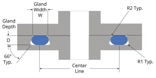
| AS568 Series | O-Ring Cross-Section | Gland Depth (D) | Gland Width (W) | Gland Corner Radii | ||||
|---|---|---|---|---|---|---|---|---|
| Nominal | TOL (+/-) | Nominal | TOL (+/-) | Nominal | TOL (+/-) | R1 | R2 | |
| -0XX | 0.070 | 0.003 | 0.052 | 0.002 | 0.064 | 0.002 | 0.015 | 0.005 |
| -1XX | 0.103 | 0.004 | 0.078 | 0.003 | 0.088 | 0.003 | 0.015 | 0.01 |
| -2XX | 0.139 | 0.004 | 0.106 | 0.003 | 0.120 | 0.003 | 0.031 | 0.01 |
| -3XX | 0.210 | 0.005 | 0.164 | 0.004 | 0.176 | 0.003 | 0.031 | 0.015 |
| -4XX | 0.275 | 0.006 | 0.215 | 0.004 | 0.235 | 0.003 | 0.063 | 0.015 |
Static gland seal
If there is a pre-designed gap between the surfaces of two mating components, a static seal ring is typically used. This is common in installation scenarios where one component is inserted into another component with a pre-existing gap.
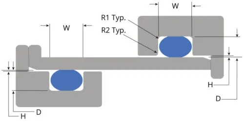
| AS568 Series | O-Ring Cross-Section | Gland Depth (D) | Squeeze | Gland Width (W) | Gap (H) | Gland Corner Radii | ||||||
|---|---|---|---|---|---|---|---|---|---|---|---|---|
| Nominal | TOL (+/-) | Actual | Percent | Nominal | TOL (+/-) | w/ 1 Backup Ring | w/ 2 Backup Rings | MAX | R1 | R2 | ||
| -0XX | 0.070 | 0.003 | .050-0.052 | .015-.023 | 22%-32% | 0.095 | 0.002 | 0.140 | 0.207 | 0.002 | 0.007 | 0.005 |
| -1XX | 0.103 | 0.004 | .081-.083 | .017-.025 | 17%-24% | 0.142 | 0.003 | 0.173 | 0.240 | 0.002 | 0.007 | 0.005 |
| -2XX | 0.139 | 0.004 | .111-.113 | .022-.032 | 16%-23% | 0.189 | 0.003 | 0.210 | 0.277 | 0.002 | 0.017 | 0.005 |
| -3XX | 0.210 | 0.005 | .170-.173 | .032-.045 | 15%-21% | 0.283 | 0.003 | 0.313 | 0.412 | 0.003 | 0.027 | 0.005 |
| -4XX | 0.275 | 0.006 | .226-.229 | .040-.055 | 15%-20% | 0.377 | 0.003 | 0.410 | 0.540 | 0.003 | 0.027 | 0.005 |
Dynamic Gland Seal
When two mating components need to move relative to each other while maintaining a tight seal, a dynamic sealing solution should be used. In such cases, a reasonable gap must always be maintained between the contact surfaces of the two components to meet the movement requirements.
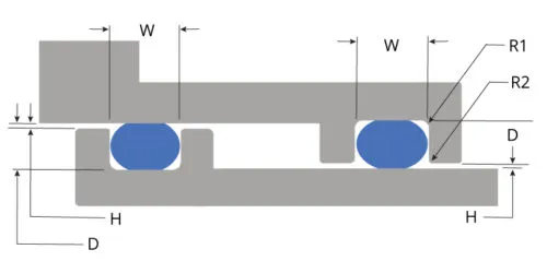
| AS568 Series | O-Ring Cross-Section | Gland Depth (D) | Squeeze | Gland Width (W) | Gap (H) | Gland Corner Radii | ||||||
|---|---|---|---|---|---|---|---|---|---|---|---|---|
| Nominal | TOL (+/-) | Actual | Percent | Nominal | TOL (+/-) | w/ 1 Backup Ring | w/ 2 Backup Rings | MAX | R1 | R2 | ||
| -0XX | 0.070 | 0.003 | .055-0.057 | .010-.018 | 15%-25% | 0.095 | 0.002 | 0.140 | 0.207 | 0.002 | 0.007 | 0.005 |
| -1XX | 0.103 | 0.004 | .088-.090 | .010-.018 | 10%-17% | 0.142 | 0.003 | 0.173 | 0.240 | 0.002 | 0.007 | 0.005 |
| -2XX | 0.139 | 0.004 | .121-.123 | .012-.022 | 9%-16% | 0.189 | 0.003 | 0.210 | 0.277 | 0.002 | 0.017 | 0.005 |
| -3XX | 0.210 | 0.005 | .185-.188 | .017-.030 | 8%-14% | 0.283 | 0.003 | 0.313 | 0.412 | 0.003 | 0.027 | 0.005 |
| -4XX | 0.275 | 0.006 | .237-.240 | .029-.044 | 11%-16% | 0.377 | 0.003 | 0.410 | 0.540 | 0.003 | 0.027 | 0.005 |
Trench Design Considerations
The design tables listed above are all compiled based on industry best practices, and their core components include key technical parameters such as compression ratio, O-ring extrusion resistance, sealing surface concentricity, diameter clearance control, and support ring selection.
Compression ratio
Our design guidelines begin with nominal dimensions (also called specified dimensions) and then consider the tolerances of various design elements, providing an accurate basis for the design of glands and grooves. A friendly reminder: Designers need to strike a balance between different dimensional parameters; the final design must be able to accommodate variations in tolerance ranges.
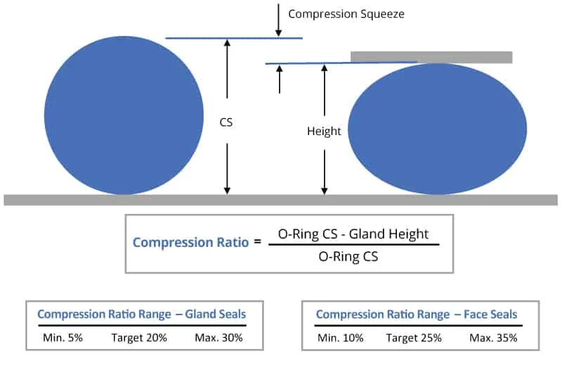
The calculations above are all based on nominal dimensions (also called specified dimensions). However, when designing grooves, two extreme cases must be considered: First, the O-ring size is too large (reaching the upper tolerance limit) while the gland height is too small (reaching the lower tolerance limit); second, the O-ring cross-sectional dimension is too small (reaching the lower tolerance limit) while the gland size is too large (reaching the upper tolerance limit).
These two cases will result in the highest and lowest compression ratios, respectively. Remember, whether it’s the compression ratio corresponding to the nominal size or the compression ratio in these two extreme cases, the value must be between 5% and 30% to be considered acceptable.
Calculate the dimensions of the O-ring connector.
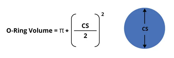
The sealing groove used to fix the O-ring adopts a rectangular structure. The design process is as follows: determine the cross-sectional specifications of the O-ring → calculate the height of the sealing groove (to meet the preset compression requirements of the O-ring) → finally calculate the width of the sealing groove. To determine the minimum accommodating area required by the sealing groove, the total volume of the O-ring must first be calculated, and then the parameters of the rectangular sealing groove that fits that volume must be matched. The following is the formula for calculating the volume based on the cross-sectional dimensions of the O-ring.
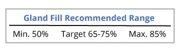
The formulation of the target filling rate recommendation for the sealing groove takes into account a number of key factors affecting the O-ring’s accommodating volume, including the space reserved for thermal expansion, the material swelling effect caused by medium contact, and the impact of tolerance fluctuations during groove processing and O-ring molding.
O-ring extrusion
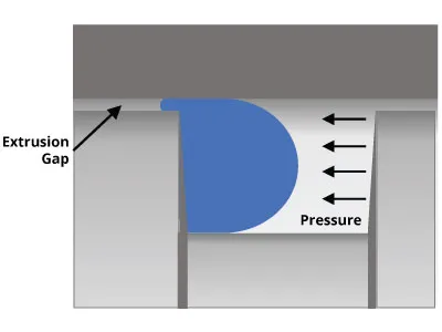
Extrusion deformation is a key failure risk to consider in the design of radial seals, especially in applications where moving parts have design clearances—such as the fit clearances between the piston and cylinder, or the piston rod and cylinder. The failure mechanism is that when unilateral pressure is high, the O-ring can easily be squeezed into narrow gaps and damaged. Therefore, the overall design of the sealing system must include this type of design clearance as a core consideration.
Concentricity and diameter gap
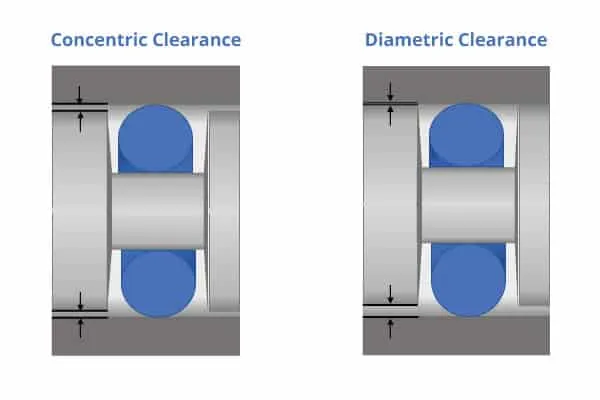
In sealing system design, if the concentricity of the cylinder and piston (or piston rod) is not constrained by bearings, it must be assumed that all mating clearances may have a unilateral offset. The clearance value under this offset state is the reference clearance parameter to be used in the extrusion protection design.
Extrusion Design Limits
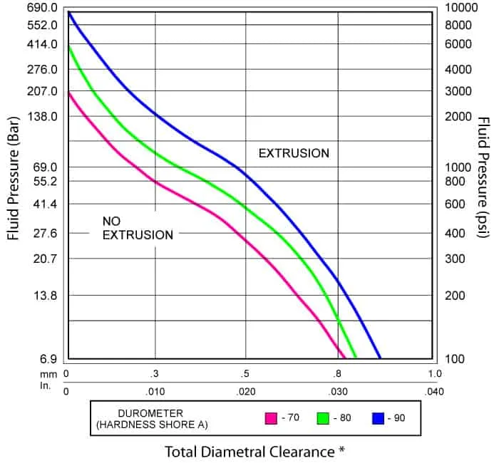
In seal design, there are several ways to address the problem of O-rings being crushed: Use bearings or alignment structures to reduce the maximum permissible gap between components, allowing the same O-ring to withstand higher pressures; or use a harder sealing material to increase its pressure resistance while maintaining the same gap size.
For more information on O-ring pressure resistance, click here.
Another method is to install an anti-extrusion support ring. These support rings are made of thin, hard plastics such as nylon, polytetrafluoroethylene (PTFE), and polyetheretherketone (PEEK), which fill and block the gap between components. The extrusion performance table below lists the maximum pressures that O-rings with different gaps and hardnesses can withstand. If adjusting the gap and material hardness is not feasible, it is recommended to use a support ring to solve the extrusion problem.
Backup ring layout
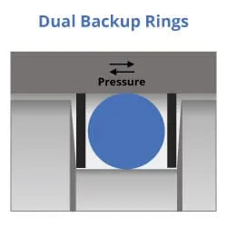
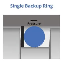
Support rings are designed to eliminate extrusion gaps in high-pressure sealing applications. If the pressure is unidirectional, only one support ring is needed. If the pressure is bidirectional, it is recommended to place one support ring on each side of the O-ring. When calculating the groove width, the increase in support ring size should be factored into the filler volume. Finally, support rings can be flat (solid, open, or spiral) or curved.
O-Ring Groove Design: Frequently Asked Questions
What is an O-ring groove (gland)?
An O-ring groove (or gland) is the machined space that holds an O-ring in place and compresses it to create a reliable seal.
How do I calculate O-ring groove dimensions?
Groove dimensions are determined by the O-ring’s inside diameter (ID), cross-section (CS), application type (static or dynamic), and the recommended squeeze and gland fill.
How much should an O-ring be squeezed?
For most applications, an O-ring should be compressed by 10–30% of its cross-section. The exact amount depends on the seal type and operating conditions.
How deep should an O-ring groove be?
The groove depth should allow the O-ring to achieve the recommended compression, typically leaving 70–90% of the O-ring cross-section after installation.
What is the difference between a static and a dynamic gland?
A static gland seals between surfaces that do not move, while a dynamic gland seals between moving parts and requires lower friction and more precise groove design.
What gland fill percentage should I design to?
A gland fill of 75–85% is recommended for most applications. This provides enough space for O-ring expansion while maintaining an effective seal.
When do I need a backup ring?
Use a backup ring in high-pressure applications (typically above 1,500 psi / 10 MPa) or when there is a large clearance gap that could cause O-ring extrusion.
What do the gland corner radii (R1 and R2) mean?
R1 and R2 are the corner radii of the groove. Proper radii reduce the risk of cutting or damaging the O-ring during installation and improve sealing performance.