
O-Ring Cord Tolerances
Why O-Ring Cord Tolerances Matter
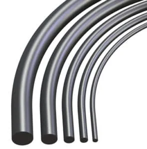
O-ring cord is widely used to manufacture custom-sized O-rings for equipment where standard dimensions are unavailable or impractical. While material selection is important, dimensional tolerance is equally critical because it directly influences compression, joint quality, and long-term sealing performance.Even a high-quality elastomer can fail to provide an effective seal if the cord diameter varies beyond the acceptable range. Maintaining consistent tolerances helps ensure uniform compression, easier assembly, and reliable sealing in both static and low-speed dynamic applications.
What Is an O-Ring Cord Tolerance?
An O-ring cord tolerance defines the allowable variation in the cross-sectional diameter of the cord during manufacturing. Because elastomer materials naturally expand and shrink during curing, a controlled tolerance ensures that the finished product remains within specified dimensional limits.
Consistent tolerances help manufacturers produce vulcanized O-rings with predictable compression and reliable sealing characteristics.
Typical factors influencing dimensional variation include:
- Rubber compound formulation
- Extrusion accuracy
- Curing process
- Material shrinkage
- Production quality control
Cross-Sectional Tolerances (Inches)
| Cross Section | E1 | E2 | E3 |
|---|---|---|---|
| .000 – .059 | +/- .006 | +/- .010 | +/- .015 |
| .060 – .099 | +/- .008 | +/- .014 | +/- .020 |
| .100 – .159 | +/- .010 | +/- .016 | +/- .027 |
| .160 – .249 | +/- .014 | +/- .020 | +/- .031 |
| .250 – .389 | +/- .016 | +/- .027 | +/- .039 |
| .390 – .629 | +/- .020 | +/- .031 | +/- .051 |
| .630 – .979 | +/- .027 | +/- .039 | +/- .063 |
| .980 – 1.569 | +/- .031 | +/- .051 | +/- .079 |
| 1.570 – 2.479 | +/- .039 | +/- .063 | +/- .098 |
| ≥ 2.480 | +/- .051 | +/- .079 | +/- .126 |
The three classes of tolerances are:
- Class I (E1) – High Precision
- Class 2 (E2) – Precision
- Class 3 (E3) – Commercial
Cross-Sectional Tolerances (Metric)
| Cross Section | E1 | E2 | E3 |
|---|---|---|---|
| 0.00 – 1.49 | +/- .150 | +/- .250 | +/- .400 |
| 1.50 – 2.49 | +/- .200 | +/- .350 | +/- .500 |
| 2.50 – 3.99 | +/- .250 | +/- .400 | +/- .700 |
| 4.00 – 6.29 | +/- .350 | +/- .500 | +/- .800 |
| 6.30 – 9.99 | +/- .400 | +/- .700 | +/- 1.00 |
| 10.00 – 15.99 | +/- .500 | +/- .800 | +/- 1.30 |
| 16.00 – 24.99 | +/- .700 | +/- 1.00 | +/- 1.60 |
| 25.00 – 39.99 | +/- .800 | +/- 1.30 | +/- 2.00 |
| 40.00 – 62.99 | +/- 1.00 | +/- 1.60 | +/- 2.50 |
| ≥ 63.00 | +/- 1.30 | +/- 2.00 | +/- 3.20 |
At KODA, we require all our factories to produce O-ring ropes to high precision (E1) tolerance standards. However, due to the expansion and contraction characteristics of rubber ropes, their cross-sectional dimensions may change slightly over time. Therefore, we guarantee that all ropes sold meet precision (E2) tolerance standards. For Viton® ropes, our factory’s tolerance standards are higher than high precision (E1), so we can produce products that meet high precision (E1) tolerance standards. For customers with E1 or more stringent tolerance requirements, we will strive to meet those needs.
Why Dimensional Consistency Is Important
Stable Compression
A uniform cord diameter allows the seal to compress evenly inside the groove. Inconsistent dimensions may create localized high or low compression, increasing the risk of leakage or premature wear.
Reliable Vulcanized Joints
When O-ring cord is joined to create custom diameters, matching cross-sections are essential for producing a strong, smooth joint. Variations in diameter can affect joint alignment and sealing integrity.
Easier Installation
Cord with controlled tolerances fits more consistently into grooves, reducing installation difficulties and minimizing the chance of twisting or deformation during assembly.
Factors to Consider When Selecting O-Ring Cord
Choosing the right cord involves more than matching the diameter.
Engineers should also evaluate:
- Operating temperature
- Chemical compatibility
- Required compression ratio
- Groove dimensions
- Joint location
- Pressure conditions
- Expected service life
The correct balance between material properties and dimensional accuracy helps improve overall sealing reliability.
Available Elastomer Materials
O-ring cord is available in a variety of compounds to suit different applications.
NBR (Nitrile)
Suitable for hydraulic oils, lubricants, and general industrial equipment.
FKM (Viton®)
Recommended for high-temperature environments, fuels, and aggressive chemicals.
EPDM
Ideal for water, steam, outdoor exposure, and many cleaning solutions.
Silicone (VMQ)
Provides excellent flexibility over a wide temperature range and is commonly used in food, medical, and electronic applications.
HNBR
Offers improved mechanical strength and heat resistance for demanding automotive and industrial systems.
Material selection should always be based on the operating environment rather than dimensional requirements alone.
Best Practices for Custom O-Ring Manufacturing
To achieve reliable sealing performance, consider the following recommendations:
- Use cord with consistent dimensional tolerances.
- Select a material compatible with the operating media and temperature.
- Prepare clean, square-cut ends before vulcanization.
- Ensure the joint is fully cured and properly aligned.
- Verify groove dimensions before installation.
Attention to these details helps improve seal durability and reduces the likelihood of early leakage.
Choosing Quality O-Ring Cord for Long-Term Reliability
Dimensional tolerance is a key factor in the performance of custom O-rings. Consistent cord diameter supports uniform compression, stronger vulcanized joints, and more dependable sealing throughout the service life of the equipment.
Whether used in industrial maintenance, OEM production, or custom sealing projects, high-quality O-ring cord with controlled tolerances provides a reliable foundation for effective sealing solutions.
Standard Cord Cross Sections and Tolerances
The table below summarizes the standard specifications of various materials and hardness ropes that our company regularly supplies. All dimensional tolerances comply with the ARPM E2 grade standard in the table above. The table also lists the minimum and maximum limit dimensions of the cross-section of each rope specification. If your working conditions require higher precision or tolerances stricter than the standard range, please communicate with us in advance before placing an order, and we will customize an adaptation solution for you.
| Inch | MM | Common Name | Tolerance | Low | High |
|---|---|---|---|---|---|
| .039 | 1 | 1 MM | +/- .010 | 0.029 | 0.049 |
| .063 | 1.6 | 1/16” Actual | +/- .014 | 0.049 | 0.077 |
| .070 | 1.8 | 1/16” Nominal | +/- .014 | 0.056 | 0.084 |
| .079 | 2 | 2 MM | +/- .014 | 0.065 | 0.093 |
| .093 | 2.4 | 3/32” Actual | +/- .014 | 0.079 | 0.107 |
| .103 | 2.6 | 3/32” Nominal | +/- .016 | 0.087 | 0.119 |
| .118 | 3 | 3 MM | +/- .016 | 0.102 | 0.134 |
| .125 | 3.2 | 1/8” Actual | +/- .016 | 0.109 | 0.141 |
| .139 | 3.5 | 1/8” Nominal | +/- .016 | 0.123 | 0.155 |
| .157 | 4 | 4 MM | +/- .016 | 0.141 | 0.173 |
| .177 | 4.5 | 4.5 MM | +/- .020 | 0.157 | 0.197 |
| .188 | 4.8 | 3/16” Actual | +/- .020 | 0.168 | 0.208 |
| .196 | 5 | 5 MM | +/- .020 | 0.176 | 0.216 |
| .210 | 5.3 | 3/16” Nominal | +/- .020 | 0.19 | 0.23 |
| .218 | 5.5 | 7/32” | +/- .020 | 0.198 | 0.238 |
| .224 | 5.7 | 5.7 MM | +/- .020 | 0.204 | 0.244 |
| .236 | 6 | 6 MM | +/- .020 | 0.216 | 0.256 |
| .250 | 6.4 | 1/4” Actual | +/- .027 | 0.223 | 0.277 |
| .275 | 7 | 1/4” Nominal, 7MM | +/- .027 | 0.248 | 0.302 |
| .295 | 7.5 | 7.5 MM | +/- .027 | 0.268 | 0.322 |
| .313 | 8 | 5/16” | +/- .027 | 0.286 | 0.34 |
| .330 | 8.4 | 8.4 MM | +/- .027 | 0.303 | 0.357 |
| .354 | 9 | 9 MM | +/- .027 | 0.327 | 0.381 |
| .375 | 9.5 | 3/8” | +/- .027 | 0.348 | 0.402 |
| .393 | 10 | 10 MM | +/- .031 | 0.362 | 0.424 |
| .437 | 11.1 | 7/16” | +/- .031 | 0.406 | 0.468 |
| .472 | 12 | 12 MM | +/- .031 | 0.441 | 0.503 |
| .500 | 12.7 | 1/2” | +/- .031 | 0.469 | 0.531 |
| .550 | 14 | 14 MM | +/- .031 | 0.519 | 0.581 |
| .562 | 14.3 | 9/16” | +/- .031 | 0.531 | 0.593 |
| .590 | 15 | 15 MM | +/- .031 | 0.559 | 0.621 |
| .625 | 15.9 | 5/8” | +/- .031 | 0.594 | 0.656 |
| .688 | 17.5 | 11/16” | +/- .039 | 0.649 | 0.727 |
| .750 | 19.1 | 3/4” | +/- .039 | 0.711 | 0.789 |
| .813 | 20.7 | 13/16” | +/- .039 | 0.774 | 0.852 |
| .875 | 22.2 | 7/8” | +/- .039 | 0.836 | 0.914 |
| 1.000 | 25.4 | 1” | +/- .051 | 0.949 | 1.051 |
| 1.125 | 28.6 | 1-1/8” | +/- .051 | 1.074 | 1.176 |
| 1.250 | 31.8 | 1-1/4” | +/- .051 | 1.199 | 1.301 |
| 1.375 | 34.9 | 1-3/8” | +/- .051 | 1.324 | 1.426 |
| 1.500 | 38.1 | 1-1/2” | +/- .051 | 1.449 | 1.551 |