
Rotary shaft seals and oil seals are widely used in industrial machinery, automotive systems, agricultural equipment, pumps, gearboxes, electric motors, and power transmission assemblies. Although these terms are often used interchangeably, choosing a reliable sealing solution requires more than matching a product name or checking its dimensions. Engineers and maintenance teams must consider shaft speed, fluid compatibility, temperature, pressure, contamination, surface finish, and installation conditions.
A seal that performs well in a low-speed gearbox may not be suitable for a high-speed motor or a system exposed to aggressive chemicals. Similarly, a replacement seal with the correct shaft diameter can still leak if the housing bore is damaged, the material is incompatible with the lubricant, or the shaft has excessive runout.
🔎 Important selection principle
Select the sealing design according to the actual motion, operating environment, and sealing requirements. Confirm dimensions, material, speed, pressure, temperature, and shaft condition before ordering a replacement.
What Is a Rotary Shaft Seal?
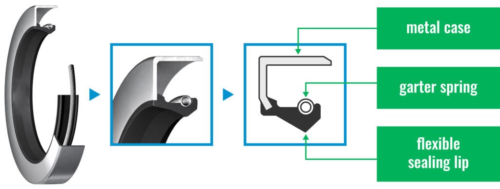
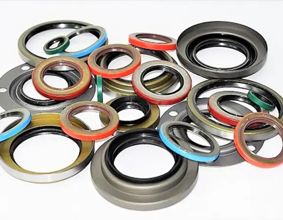
A rotary shaft seal is a dynamic sealing component that controls the passage of lubricant or contaminants between a rotating shaft and a stationary housing. In many industrial applications, the seal retains oil or grease inside a bearing or gearbox while helping prevent dust, moisture, and other foreign particles from entering the assembly.
A conventional radial shaft oil seal commonly incorporates an elastomer sealing lip, a metal reinforcement case, and a garter spring that helps maintain contact between the lip and the shaft. Depending on the application, additional dust-exclusion lips, specialized lip geometries, or alternative sealing materials may be used.
The sealing lip operates at a dynamic interface. Its performance depends on contact pressure, lubricant availability, surface finish, shaft speed, temperature, and the amount of shaft movement. When these factors are properly controlled, the seal can maintain a stable sealing interface while limiting friction and wear.
Rotary shaft seals are commonly used in:
- Industrial gearboxes and speed reducers.
- Electric motors, generators, and power transmission equipment.
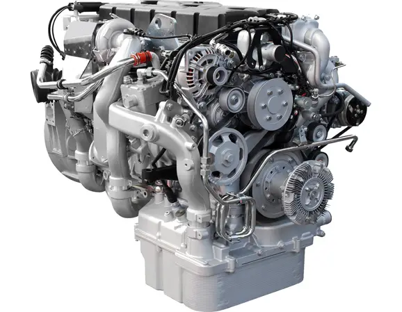
- Automotive engines, transmissions, differentials, and wheel hubs.
- Agricultural and construction machinery.
- Pumps, compressors, and rotating process equipment.
- Bearings and other lubricant-retaining assemblies.
For technical background, consult the SKF industrial seals resources and the SKF Industrial Shaft Seals catalogue.
Rotary Shaft Seals vs. Oil Seals: Is There a Difference?
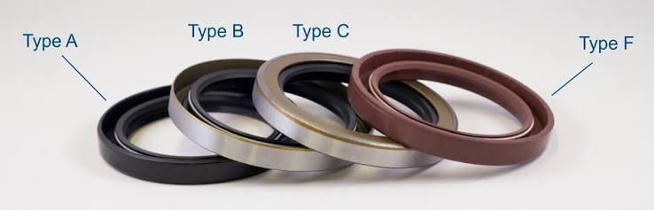
In common industrial usage, an oil seal is a type of rotary shaft seal, and the terms frequently describe the same family of radial lip seals. The terminology varies by industry, equipment type, and supplier. The more important distinction is the sealing function and design rather than the wording used in a catalogue.
| Term | Typical meaning | Primary function |
|---|---|---|
| Rotary shaft seal | A broad term for a seal used where rotary motion occurs. | Control leakage and contamination at rotating interfaces. |
| Oil seal | Commonly refers to a radial lip seal used to retain oil or grease. | Retain lubricant and help exclude external contaminants. |
| Lip seal | Describes a sealing component that uses a flexible lip to form the sealing interface. | Provide contact sealing against a shaft or another moving surface. |
| Static O-ring | An elastomer ring compressed between stationary mating surfaces. | Seal a fixed joint without continuous relative motion. |
| Hydraulic rod seal | A seal designed primarily for reciprocating linear movement. | Control fluid leakage along a moving piston rod. |
Practical takeaway: When a supplier lists an oil seal and a rotary shaft seal separately, verify the exact construction, dimensions, lip profile, material, and application. Similar names do not guarantee that two parts are interchangeable.
How Rotary Shaft Seals Differ from Static O-Rings and Hydraulic Seals
Rotary Shaft Seals vs. Static O-Rings
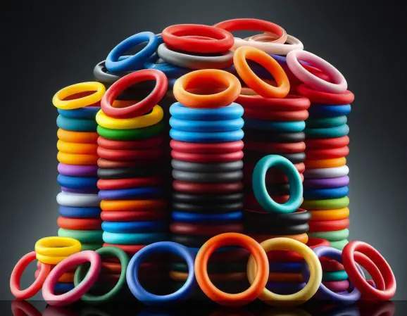
A static O-ring seals a stationary joint by being compressed within a properly designed groove. Because the mating surfaces do not continuously move relative to each other, frictional wear at the sealing interface is generally less significant than in a dynamic application.
A rotary shaft seal must maintain its sealing function while a shaft rotates beneath the lip. This introduces additional engineering requirements involving friction, heat generation, shaft surface finish, rotational speed, lubrication, and wear resistance.
An O-ring can be used in certain rotary sealing arrangements, but it should not automatically replace a dedicated rotary shaft seal. High-speed rotary O-ring applications require careful groove design, controlled shaft movement, appropriate compound selection, and management of frictional heat.
For further design guidance, consult the Parker O-Ring Handbook.
Rotary Shaft Seals vs. Hydraulic Rod Seals
Hydraulic rod seals are designed primarily for reciprocating motion, where a rod moves back and forth through the sealing element. Depending on the application, they may operate under substantial hydraulic pressure and are often installed with guide rings, wipers, and other components.
Conventional rotary shaft seals are generally intended for continuous rotary movement and comparatively low pressure. Their lip geometry and material selection are optimized for a different combination of motion, friction, and leakage control.
Using a standard rotary oil seal in a high-pressure hydraulic application can lead to lip deformation, extrusion, excessive friction, or premature failure. Always verify whether the application requires a dedicated pressure-rated rotary seal, a hydraulic rod seal, or another engineered sealing arrangement.
Key Factors for Selecting the Right Rotary Shaft Seal
1. Shaft Speed and Surface Velocity
Rotational speed directly influences the heat and wear generated at the sealing interface. As shaft speed increases, the lip must operate under more demanding frictional conditions. A material or lip design suitable for a slow gearbox may not provide acceptable service life in a high-speed motor.
When assessing speed, do not consider revolutions per minute in isolation. Shaft diameter also affects the linear speed of the sealing surface. Two shafts running at the same RPM can impose very different conditions on the seal if their diameters differ.
For a cylindrical shaft, approximate surface speed can be calculated as:
Surface speed
\(v = \frac{\pi d n}{60}\)
where \(v\) is surface speed in m/s, \(d\) is shaft diameter in metres, and \(n\) is rotational speed in revolutions per minute.
This calculation provides the shaft surface velocity, not the allowable operating speed of the seal. The permitted speed depends on the seal design, material, lubrication, temperature, pressure, shaft finish, and manufacturer’s specifications.
Selection advice: Compare the calculated surface speed with the technical limits for the specific seal. If speed is high, evaluate low-friction lip designs, specialized compounds, or PTFE-based sealing solutions where appropriate.
2. Pressure Differential
Pressure is a critical selection factor because many conventional radial oil seals are designed primarily for low-pressure service. Sustained pressure or repeated pressure spikes can increase lip loading, raise friction, deform the seal, or force lubricant past the sealing edge.
Before selecting a seal, establish whether the application is vented, exposed to minor pressure fluctuations, or subject to continuous positive pressure. Check whether the breather, return passage, or pressure-control system is functioning correctly.
Where pressure exceeds the standard design limits, select a purpose-designed pressure-rated seal or another sealing configuration recommended by the equipment manufacturer. Do not assume that a thicker elastomer lip alone will solve a pressure-related problem.
3. Fluid and Chemical Compatibility
The working fluid affects swelling, shrinkage, hardness, elasticity, wear, and long-term material stability. Petroleum-based oils, synthetic lubricants, fuels, refrigerants, cleaning agents, and process chemicals may require different compounds.
When checking compatibility, consider the complete fluid formulation rather than only its general category. Additives, temperature, contamination, and the duration of exposure can change how a sealing material performs.
For critical machinery, request compound-specific compatibility information from the seal supplier. If the fluid is unusual or the consequences of failure are significant, testing under representative conditions may be necessary.
4. Operating Temperature
Temperature affects both the elastomer and the lubricant. Excessive heat may accelerate aging, reduce elasticity, increase wear, or cause chemical degradation. Low temperatures can make some materials less flexible and reduce their ability to follow shaft movement.
Determine the minimum startup temperature, normal operating temperature, peak temperature, and any short-term temperature excursions. A seal must be suitable for the actual operating range, not just the average temperature recorded during routine operation.
Also investigate the source of excessive heat. Poor lubrication, excessive lip loading, shaft misalignment, bearing problems, and trapped grease can create local heating that may not be reflected by the general machine temperature.
5. Shaft Finish, Runout, and Alignment
The shaft surface and its movement relative to the housing strongly influence sealing performance. A shaft that is too rough can accelerate lip wear, while scratches or corrosion can create leakage paths. Excessive runout or eccentricity can prevent the lip from maintaining consistent contact around the shaft.
Before replacing a seal, inspect the sealing track, measure critical dimensions, and verify runout and alignment where required. The correct limits depend on the seal design and equipment specification; do not apply one universal surface-finish or runout value to every application.
If the shaft has a wear groove, investigate whether a suitable repair sleeve or approved shaft repair can restore the sealing surface. The repaired dimensions and surface condition must remain suitable for the selected seal.
6. Contamination and Environmental Exposure
Dust, water, mud, abrasive particles, and corrosive chemicals can damage the lip and shaft. Equipment operating outdoors or in agricultural, mining, construction, or washdown environments may need stronger contamination exclusion than equipment installed in a clean indoor facility.
Consider whether a single-lip seal is sufficient or whether an auxiliary dust lip, a separate exclusion seal, a labyrinth arrangement, or another protective feature is needed. The correct solution depends on the type and amount of contamination, the available space, shaft speed, and lubrication arrangement.
Additional exclusion features must also be selected carefully because extra lip contact can increase friction and heat. More lips do not automatically mean better performance in every application.
Choosing the Right Seal Material
Material selection should follow the operating conditions rather than price or availability alone. The compounds below are common options, but their usable temperature and chemical resistance depend on the exact formulation and seal design.
| Material | Typical strengths | Important considerations |
|---|---|---|
| NBR | Often suitable for general-purpose mineral oils, greases, and many petroleum-based lubricants. | Verify actual temperature limits, fluid chemistry, and resistance to additives. |
| FKM | Often selected for elevated temperatures and many oils, fuels, and chemically demanding environments. | Compatibility varies by compound; check low-temperature performance and specific chemicals. |
| HNBR | Can provide improved heat, wear, and mechanical performance in suitable applications. | Confirm compatibility with the lubricant, temperature range, and mechanical loading. |
| Silicone | Useful in selected applications requiring a broad temperature capability. | Assess wear resistance, mechanical strength, and compatibility with the working fluid. |
| PTFE | Can offer low friction and strong chemical resistance in specialized seal designs. | Check shaft finish, installation procedure, compound grade, and application-specific limits. |
Material selection should not be based on polymer name alone. Compound formulation, lip geometry, shaft finish, lubrication, and operating conditions can significantly affect performance.
For more detailed information, consult the SKF industrial seal resources and the Parker O-Ring Handbook.
Common Rotary Shaft Seal Designs
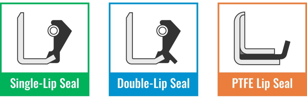
Single-Lip Oil Seals
A single-lip oil seal uses one primary sealing lip to retain lubricant or control leakage. It is often appropriate for relatively clean environments where contamination exclusion requirements are modest.
Advantages may include a compact design, low complexity, and reduced friction compared with some multi-lip configurations. Suitability still depends on the actual speed, lubricant, shaft condition, and seal construction.
Double-Lip Seals with a Dust Excluder
A double-lip design may include a primary lip for lubricant retention and a secondary lip intended to exclude dust or moisture. These designs are commonly considered for outdoor machinery, agricultural equipment, wheel hubs, and other environments with elevated contamination risk.
The secondary lip can improve protection, but it may also increase friction and heat. Confirm whether the auxiliary lip requires lubrication and whether the design suits the expected speed and environmental exposure.
Spring-Loaded Radial Shaft Seals
A garter spring helps maintain contact force at the primary sealing lip as the material wears and operating conditions change. Spring-loaded radial seals are widely used for retaining oil in rotating equipment, although the correct design depends on speed, pressure, fluid, and the manufacturer’s performance limits.
During inspection, a displaced, corroded, or damaged spring can be evidence of installation damage, severe wear, or an unsuitable operating environment.
PTFE Lip Seals
PTFE-based rotary seals are used in applications where low friction, chemical resistance, temperature capability, or specialized operating requirements make conventional elastomer lips less suitable. Depending on the design and compound, PTFE seals may accommodate higher surface speeds or certain conditions that are difficult for standard elastomeric seals.
However, PTFE seals are not universal drop-in replacements. Their installation methods, shaft requirements, lip geometry, and operating limits may differ from conventional rubber oil seals. Follow the specific manufacturer’s recommendations.
See SKF’s PTFE seal technical information for additional design considerations.
Non-Contacting Seals and Labyrinth Designs
Not every rotary sealing application requires a lip that continuously contacts the shaft. Labyrinth seals and other non-contacting designs can be useful for contamination exclusion or grease-retaining arrangements where a controlled leakage path is acceptable.
Because non-contacting designs operate differently from conventional contact lip seals, they should not be assumed to provide the same oil-retention performance in every application. Select the arrangement according to the required leakage control, contamination level, speed, and lubrication method.
How to Confirm the Correct Seal Dimensions
Rotary shaft seals are commonly specified using three principal dimensions: shaft diameter, housing bore diameter, and seal width. These measurements must correspond to the intended installation and should be verified against a reliable drawing or part reference.
1. Shaft diameter
Measure the shaft where the sealing lip contacts it. Check for wear grooves, corrosion, and dimensional variation before using the measurement to select a replacement.
2. Housing bore diameter
Measure the bore that retains the seal. Inspect the bore for scratches, distortion, corrosion, and other damage that may affect the fit.
3. Seal width
Confirm the required axial width and installation depth. A seal that is too wide, too narrow, or positioned incorrectly may interfere with nearby components or fail to seal properly.
Where possible, cross-reference the original equipment part number and verify the dimensions using a manufacturer’s catalogue. Avoid relying exclusively on measurements taken from a worn seal, since wear and deformation may make the original dimensions difficult to identify accurately.
Also confirm the lip arrangement, material, pressure capability, and any special requirements for rotation or contamination exclusion. Correct dimensions are essential, but they do not establish application compatibility on their own.
Common Reasons a Correctly Sized Seal Still Leaks
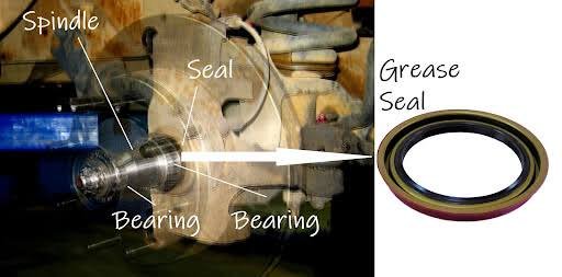
A seal may match the shaft and housing dimensions yet fail because other application requirements have not been satisfied.
| Symptom | Potential cause | Recommended check |
|---|---|---|
| Leakage immediately after installation | Damaged lip, wrong orientation, tilted fitting, or inadequate lubrication | Inspect installation damage and verify the fitting procedure. |
| Leakage after the equipment warms up | Thermal expansion, lubricant changes, excessive friction, or material limitations | Check operating temperature and fluid compatibility. |
| Repeated leakage at the same shaft position | Shaft wear groove, scoring, or corrosion | Inspect and measure the sealing track. |
| Seal lip wears unevenly | Excessive runout, misalignment, bearing wear, or vibration | Check shaft movement, bearings, and alignment. |
| Oil appears around the seal’s outer diameter | Damaged bore, incorrect fit, or deformed casing | Inspect housing dimensions and outer-diameter contact. |
| Seal fails after a long period of inactivity | Aging, corrosion, material degradation, or inadequate lubrication during startup | Review storage, idle duration, lubricant condition, and startup procedure. |
For detailed engineering guidance, consult the SKF CR Seals Handbook. Its selection guidance emphasizes evaluating the combined effects of temperature, speed, pressure differential, lubricant, runout, and shaft-to-bore misalignment.
Can a Shaft Repair Sleeve Solve a Recurring Leak?
A shaft repair sleeve may be an effective option when the shaft is structurally sound but the sealing track has developed a wear groove, corrosion, or localized surface damage. The sleeve provides a new sealing surface without necessarily requiring complete shaft replacement.
This approach can reduce repair cost and downtime, especially for equipment where shaft removal is difficult. However, it is not suitable for every shaft or every type of damage.
Before using a repair sleeve, verify:
- The shaft can accommodate the sleeve without interfering with adjacent components.
- The sleeve dimensions and installation method are suitable for the shaft and application.
- The resulting sealing surface meets the seal manufacturer’s requirements.
- The underlying cause of abnormal wear, runout, contamination, or lubrication failure has been addressed.
- The replacement seal is compatible with the finished shaft diameter and surface condition.
A repair sleeve restores the sealing track; it does not correct excessive bearing movement, shaft misalignment, high pressure, or incompatible materials. If the root cause remains, the replacement seal may fail again.
A Practical Selection Checklist for Engineers and Buyers
Before ordering rotary shaft seals or oil seals, document the application rather than relying only on the old part number. The following checklist can help reduce selection errors and unnecessary downtime.
✓ Application requirements
- Equipment type, model, and seal installation location.
- Original part number or verified dimensional drawing.
- Shaft diameter, housing bore diameter, and seal width.
- Rotational speed and calculated shaft surface velocity.
- Normal and peak operating temperatures.
- Working fluid, lubricant formulation, and chemical exposure.
- Operating pressure and possible pressure fluctuations.
- Required dust, water, or contamination exclusion.
- Shaft finish, wear condition, runout, and alignment.
- Installation depth, orientation, and available assembly space.
For recurring failures, include photographs of the failed seal, shaft contact track, and housing bore. Record how long the seal operated before leakage appeared and whether the problem occurred during startup, at high speed, or after the equipment reached operating temperature.
This information helps the manufacturer or sealing specialist assess whether the application needs a different material, lip profile, pressure rating, installation method, or shaft repair.
Maintenance Practices That Improve Seal Reliability
Even a well-selected seal can fail prematurely if maintenance procedures allow contamination, inadequate lubrication, excessive heat, or mechanical movement to develop.
- Inspect the sealing area regularly: Look for fresh oil films, abnormal dust accumulation, and repeated fluid-level loss.
- Maintain lubricant quality: Use the specified fluid and investigate contamination, oxidation, or degradation.
- Monitor temperature and vibration: Unexpected changes may indicate friction, bearing problems, misalignment, or lubrication faults.
- Protect the shaft during maintenance: Avoid scratching the sealing track with tools and prevent debris from entering the assembly.
- Follow the approved installation procedure: Confirm orientation, insertion depth, lip protection, and required lubrication.
- Use condition-based inspection where appropriate: Track leakage, wear, operating hours, and failure patterns to support maintenance decisions.
For machinery operating in dusty, wet, or corrosive environments, review whether the current exclusion design is adequate. For high-speed applications, assess whether friction and temperature are within the limits specified by the seal manufacturer.
Frequently Asked Questions
1. Are rotary shaft seals and oil seals the same thing?
In common industrial usage, an oil seal is a type of rotary shaft seal, and both terms often refer to a radial lip seal used to retain lubricant and exclude contaminants. However, the term rotary shaft seal can cover a broader range of designs, so always verify the construction, dimensions, material, and operating limits before substituting one product for another.
2. How do I choose between NBR, FKM, HNBR, and PTFE seals?
Choose according to the working fluid, minimum and maximum temperature, shaft speed, pressure, and mechanical requirements. NBR is common in many general-purpose oil applications, while FKM and HNBR may suit more demanding thermal or chemical conditions. PTFE-based designs can be useful where low friction or specialized chemical resistance is required. Verify the specific compound and seal design with the manufacturer.
3. Why does a correctly sized rotary shaft seal still leak?
Correct dimensions alone do not guarantee performance. Leakage may result from a worn or scratched shaft, excessive runout, poor alignment, incorrect material, unsuitable pressure conditions, inadequate lubrication, or installation damage. Inspect the entire sealing system rather than replacing the seal based only on its dimensions.
4. Can a shaft repair sleeve prevent repeated oil seal leakage?
A suitable repair sleeve can restore a worn sealing track when damage is limited to the shaft surface and the shaft remains otherwise serviceable. It must meet the seal manufacturer’s dimensional and surface requirements. It will not resolve unrelated problems such as bearing wear, misalignment, excessive pressure, or incorrect material selection.
5. What information should I provide when ordering an industrial oil seal?
Provide the shaft diameter, housing bore diameter, seal width, original part number, equipment model, working fluid, temperature range, shaft speed, operating pressure, and contamination conditions. For difficult applications, include photographs of the failed seal and shaft surface, along with details of how and when leakage occurs. This information helps identify a suitable replacement and reduce the risk of repeat failure.