
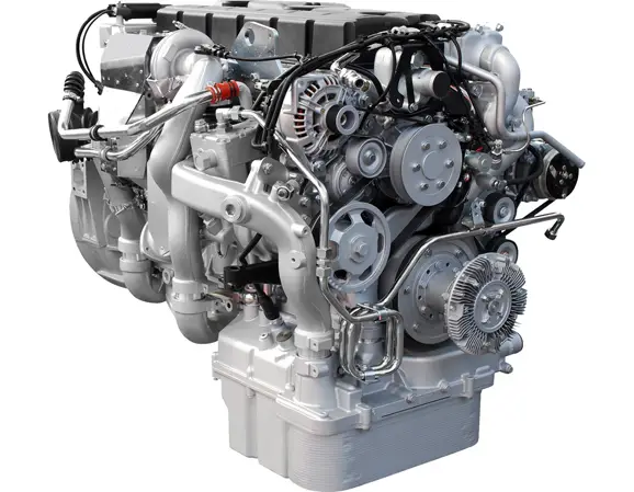

Mechanical seals are critical components in pumps, compressors, mixers, agitators, and other rotating equipment where fluid leakage must be controlled. Their performance depends not only on the quality of the seal itself, but also on correct installation, suitable material selection, shaft condition, lubrication, cooling, and operating practices.
A mechanical seal installed incorrectly can develop leakage, overheating, excessive wear, or sudden failure even when the replacement part is manufactured to the correct specification. Following a controlled installation procedure helps protect precision sealing faces, reduce unplanned downtime, and improve equipment reliability.
✓ Before installation
Confirm the mechanical seal model, installation drawing, equipment manufacturer’s instructions, process-fluid hazards, and required seal-support connections. Isolate the equipment, release pressure, drain hazardous fluids safely, and verify that the rotating machinery cannot start unexpectedly.
What Is a Mechanical Seal and How Does It Work?
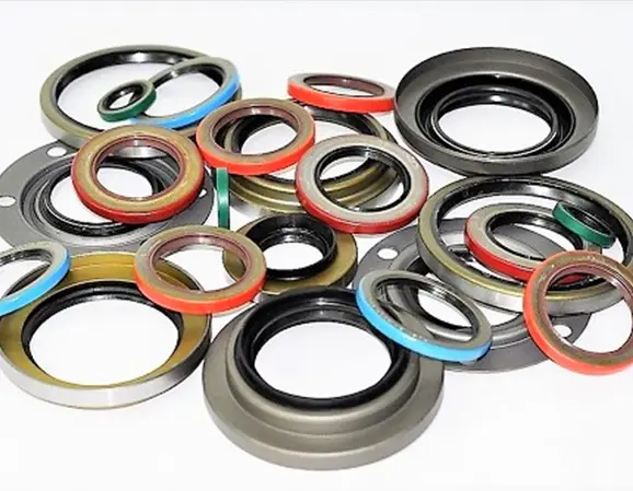
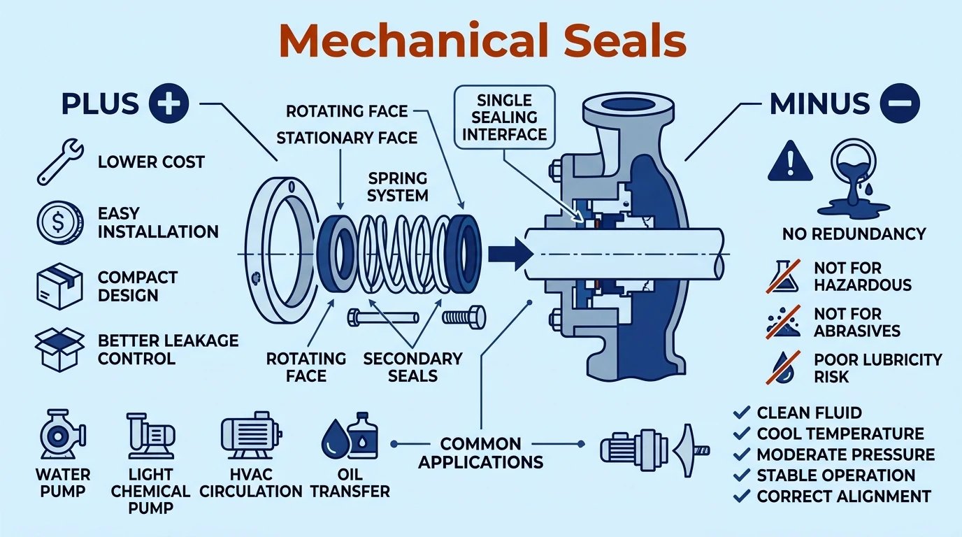
A mechanical seal is a device that limits fluid leakage between a rotating shaft and a stationary housing. Unlike a conventional oil seal, which typically uses an elastomeric lip contacting a shaft, a mechanical seal commonly relies on two finely finished sealing faces: one rotates with the shaft, while the other remains stationary in the seal housing or gland.
During operation, the sealing faces work together with a controlled microscopic fluid film or another design-specific lubrication mechanism. Springs, fluid pressure, and other loading features help maintain the intended face contact. Secondary seals, such as O-rings or bellows, prevent leakage around the supporting components.
Main Components of a Typical Mechanical Seal
- Rotating face: Attached to or driven by the rotating shaft or shaft sleeve.
- Stationary seat: Mounted in the gland or seal chamber and aligned with the rotating face.
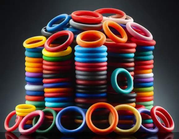
- Secondary sealing elements: O-rings, elastomer bellows, or other components that seal around the faces and supporting parts.
- Springs or loading mechanism: Provide the designed closing force and accommodate movement within the permitted range.
- Gland and retaining components: Position the seal and help maintain the correct assembly geometry.
- Support-system connections: Where specified, provide flushing, cooling, heating, barrier fluid, or buffer fluid for the selected seal arrangement.
Mechanical seals are available in different configurations, including single and double seals, balanced and unbalanced designs, cartridge seals, and component seals. The correct installation sequence, working length, spring compression, and support arrangements vary by design. Always use the instructions supplied for the exact seal model rather than applying a generic procedure to every configuration.
Why Correct Mechanical Seal Installation Matters
The sealing faces are precision-engineered surfaces. Dirt, scratches, incorrect alignment, excessive compression, or unsuitable lubrication can disturb the sealing interface. Damage to an O-ring or bellows may also create a leakage path even when the primary faces appear undamaged.
Installation quality directly influences several operating outcomes:
Leakage control
Correct face alignment and intact secondary seals help maintain the designed sealing interface.
Temperature management
Appropriate face loading and fluid circulation help control frictional heat.
Component protection
Careful assembly reduces the risk of damaged faces, distorted elastomers, and bent or displaced components.
Equipment availability
Correct installation and commissioning reduce avoidable repeat repairs and unplanned shutdowns.
For additional guidance, consult EagleBurgmann’s mechanical seal operating manual and the relevant John Crane installation and maintenance instructions. Manufacturer documentation takes precedence over general guidance because seal designs and equipment requirements differ.
Step-by-Step Mechanical Seal Installation Procedure
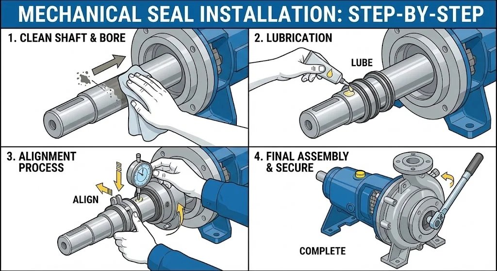
Step 1: Isolate the Equipment and Establish a Safe Work Area
Before opening a pump or other rotating machine, follow the site’s lockout/tagout procedure and the equipment manufacturer’s safety requirements. Isolate all energy sources, including electrical power, stored hydraulic or pneumatic energy, pressure, and any other source capable of causing unexpected movement.
Allow hot equipment to cool where necessary. Drain and depressurize the system, and confirm that trapped fluid has been safely managed. Process fluids may remain in the seal chamber, piping, or connected equipment after the main system has been drained.
- Verify that the machine cannot start unexpectedly.
- Confirm that pressure has been released and the equipment is in a safe condition for disassembly.
- Use appropriate personal protective equipment for the process medium and maintenance task.
- Follow site procedures for hazardous, toxic, corrosive, flammable, or environmentally harmful fluids.
Safety warning: Never loosen a seal gland or dismantle a pressurized pump. If the process fluid is hazardous or the isolation status is uncertain, stop work until a competent person has verified the equipment is safe.
Step 2: Verify the Replacement Seal and Assembly Drawing
Compare the replacement mechanical seal with the removed assembly and the approved technical documentation. Check the model, shaft diameter, gland dimensions, connection arrangement, material designation, and installation orientation. Visual similarity alone is not sufficient to confirm interchangeability.
For cartridge seals, verify the cartridge dimensions, setting devices, retaining clips, and required working position. For component seals, confirm the individual rotating and stationary parts, secondary sealing elements, springs, and retaining hardware.
Review any application-specific requirements, including pressure limits, rotational speed, temperature range, fluid compatibility, and seal-support piping. If the identification marking or documentation does not match, obtain clarification before assembly.
Step 3: Inspect the Seal Components Before Assembly
Unpack the seal in a clean work area and inspect all parts under adequate lighting. Keep protective covers on the sealing faces until the stage at which they must be removed. Avoid placing finished faces directly on a bench, metal surface, or other area that may contain abrasive particles.
Inspect the primary faces for chips, cracks, scratches, and contamination. Examine O-rings, bellows, and other secondary sealing elements for cuts, twisting, deformation, aging, or damage. Check springs and metal components for corrosion, deformation, or signs of incorrect assembly.
If a sealing face is chipped or damaged, do not assume that cleaning or polishing it on-site will restore its original performance. Precision faces may require specialist inspection, lapping, or replacement according to the seal manufacturer’s repair procedure.
Step 4: Clean the Shaft, Sleeve, and Seal Chamber
Thorough cleaning helps prevent particles from becoming trapped at the sealing interface or beneath a secondary seal. Remove old residue, deposits, corrosion, and loose material using methods compatible with the equipment and process environment.
Inspect the shaft or shaft sleeve for scratches, wear grooves, corrosion, burrs, and damage around keyways or shoulders. Check the seal chamber and gland seating surfaces for residue, distortion, and damaged locating features.
Use cleaning agents approved for the seal materials. Do not expose elastomers, coatings, or polymer parts to an unverified solvent. Lint-free wipes and clean handling tools are preferable where contamination could affect the sealing faces.
Step 5: Check Shaft Runout, Alignment, and Bearings
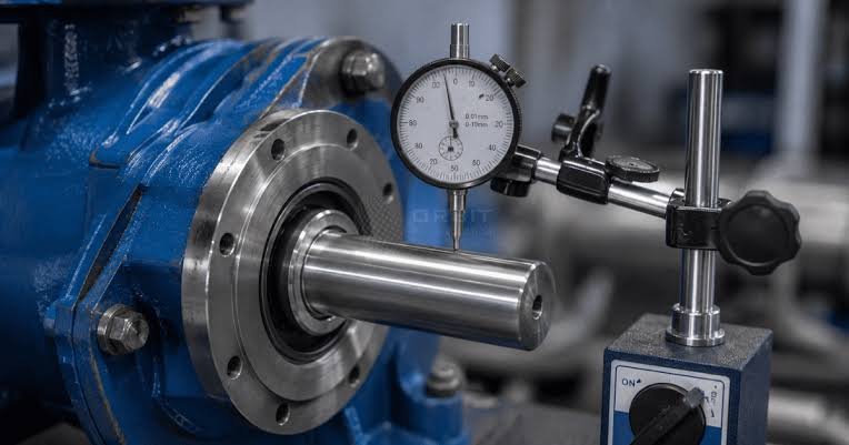
A mechanical seal cannot compensate for every shaft or equipment defect. Excessive runout, bearing wear, coupling misalignment, shaft deflection, and vibration can disrupt the sealing interface during rotation.
Measure runout and check alignment using the equipment manufacturer’s specified methods and tolerances. Inspect bearings, the shaft sleeve, coupling, and related components for wear or looseness. Verify that the seal chamber and shaft geometry meet the requirements for the selected seal.
If the equipment has a history of repeated seal failures, investigate the operating system as well as the seal. Installing a new component without correcting an underlying alignment or vibration problem may only provide temporary improvement.
Step 6: Prepare and Lubricate Secondary Seals Correctly
Some mechanical seals require a compatible lubricant on O-rings or other secondary sealing elements to facilitate assembly. Others have specific restrictions on lubricants, cleaning agents, or assembly methods. Follow the exact product instructions.
An incompatible lubricant can cause elastomer swelling, shrinkage, softening, or deterioration. This is particularly important when the seal uses materials such as EPDM, FKM, NBR, or specialized PTFE-based components, each of which has different compatibility considerations.
Avoid stretching, twisting, pinching, or rolling an O-ring into position. Check the groove for sharp edges and contamination. Where a design uses PTFE secondary seals, follow the manufacturer’s specific instructions because their assembly behavior differs from conventional elastomers.
Step 7: Install the Rotating and Stationary Components
The order of installation depends on the mechanical seal design and equipment configuration. Follow the assembly drawing to position the stationary seat, rotating assembly, springs, drive components, and secondary seals in the correct sequence.
Protect the finished faces throughout assembly. Avoid unnecessary contact between the faces and hard surfaces, and do not use the sealing faces as bearing surfaces for installation tools. Keep all parts correctly oriented and ensure that O-rings and bellows are not pinched or displaced.
Use the specified installation sleeve, setting tool, or assembly fixture where required. Do not hammer the seal into place or apply uncontrolled force to a precision component. If an assembly does not slide or seat as expected, stop and identify the source of resistance instead of forcing the parts together.
Step 8: Set the Correct Working Length or Installation Dimension
Many mechanical seals require a defined working length or setting dimension to achieve the intended face loading. Incorrect positioning can lead to insufficient contact force, excessive face loading, restricted movement, or damage to the spring mechanism.
Use the dimensions and setting instructions specified for the exact seal. Do not estimate spring compression from appearance or copy a measurement from a different seal model. For cartridge designs, leave setting devices in place or remove them only at the stage stated in the manufacturer’s instructions.
Tighten fasteners using the specified sequence and torque where provided. Uneven tightening can distort components or create misalignment. Confirm that the gland, retaining components, and shaft connections are secured as intended.
Step 9: Reassemble the Pump and Verify Free Movement
After installing the mechanical seal, reassemble the pump or rotating equipment according to the equipment manual. Check that the impeller, casing, bearing housing, coupling, gland, and related parts are correctly positioned.
Where the equipment design and safety procedure permit, rotate the shaft manually to check for abnormal binding or interference. Do not force rotation if resistance is encountered. Investigate possible misalignment, incorrect assembly, or contact between components before proceeding.
Reconnect all required flushing, cooling, barrier-fluid, buffer-fluid, drain, vent, or other support-system lines according to the approved piping plan. Check that the lines are correctly routed, connected, and free from obstructions.
Step 10: Complete Pre-Start Checks and Commissioning
Before startup, confirm that the pump is correctly assembled and that all required support systems are available. Fill and vent the equipment as specified by the manufacturer. A liquid-lubricated mechanical seal must not be operated dry unless its design is specifically intended for that mode of operation.
Check the process valves, flush connections, cooling supply, barrier or buffer system, and instrumentation. Confirm that the seal chamber has the required fluid and that personnel are clear of rotating components before restoring power.
During commissioning, monitor leakage, temperature, vibration, pressure, flow, and any seal-support-system parameters specified by the manufacturer. Stop the equipment if abnormal noise, rapid temperature rise, unexpected leakage, or other unsafe conditions occur.
Commissioning rule: Do not treat startup as a simple leak test. A seal may require a specific fluid circulation, venting sequence, cooling arrangement, or pressure condition before it can operate safely. Follow the approved startup procedure for the complete equipment system.
Mechanical Seal Materials and Compatibility
Material selection affects wear resistance, chemical compatibility, thermal behavior, and the reliability of the sealing interface. Mechanical seals often combine different face materials and secondary sealing elements, so compatibility must be evaluated for the complete assembly rather than one component in isolation.
| Material | Typical role | Important considerations |
|---|---|---|
| Carbon graphite | Common primary-face material in many liquid mechanical seals. | Grade, impregnation, fluid, temperature, pressure, and dry-running sensitivity must be checked. |
| Silicon carbide | Hard sealing-face material used in many demanding applications. | Confirm the grade, chemical environment, thermal conditions, and resistance to impact or handling damage. |
| Alumina ceramic | Used for stationary or rotating faces in suitable service conditions. | Check chemical compatibility, thermal shock risk, and the mechanical limits of the selected grade. |
| Tungsten carbide | Hard face material for applications where wear resistance is important. | Binder composition, fluid compatibility, face pairing, and operating conditions affect suitability. |
| NBR / FKM / EPDM | Elastomeric secondary sealing elements in suitable designs. | Select the specific compound for the process fluid, temperature, pressure, and assembly method. |
| PTFE-based materials | Used in selected secondary sealing and specialty sealing designs. | Follow the specified installation method and check creep, dimensional behavior, and design compatibility. |
The material names above describe broad categories rather than guaranteed performance ratings. Two compounds within the same material family can have different properties. Confirm compatibility with the actual process fluid, concentration, temperature, pressure, cleaning chemicals, and exposure duration.
For broader technical reference, visit EagleBurgmann’s download center for available product manuals and technical documentation, and John Crane’s engineering resources for information on mechanical seals and sealing-system reliability.
Mechanical Seal Types and Installation Differences
Cartridge Mechanical Seals
Cartridge seals are generally supplied as preassembled units with the sealing components positioned within a cartridge assembly. They can simplify installation by reducing the need to set individual seal components directly on the shaft. However, the correct mounting dimensions, gland alignment, fastening sequence, and handling of setting devices remain essential.
Do not remove shipping restraints, setting clips, or spacers earlier than specified. Some devices maintain the designed working position during installation and must be handled in the exact sequence stated in the product manual.
Component Mechanical Seals
Component seals are assembled from individual parts and often require more direct control over installation order and working length. The installer must verify the position of the stationary seat, rotating assembly, springs, drive features, and secondary seals against the relevant drawing.
Because the components may be handled separately, cleanliness and protection of the sealing faces are particularly important. Use the manufacturer’s fixtures and measurements where specified, and avoid improvising the setting dimension.
Single and Double Mechanical Seals
A single mechanical seal typically uses one primary sealing interface. Double-seal arrangements use two interfaces and may require a buffer or barrier-fluid system, depending on the design. These arrangements are often selected for process, safety, or reliability reasons, but they introduce additional installation and monitoring requirements.
For double seals, confirm the specified fluid, pressure relationship, circulation, temperature control, and instrumentation before startup. Never assume that a support system intended for one seal arrangement can be reused unchanged with another.
Common Mechanical Seal Installation Mistakes
| Installation mistake | Possible result | Prevention |
|---|---|---|
| Contaminating the sealing faces | Leakage paths, scoring, or accelerated wear. | Use a clean work area and keep protective covers in place until assembly. |
| Using excessive installation force | Chipped faces, damaged O-rings, distorted bellows, or displaced parts. | Use the correct tools and investigate unexpected resistance before proceeding. |
| Incorrect working length | Insufficient face loading, excessive friction, or restricted movement. | Measure and set the seal using the model-specific drawing. |
| Incompatible lubricant | Secondary-seal swelling, hardening, or chemical deterioration. | Use only approved assembly lubricants and cleaning agents. |
| Ignoring shaft runout or bearing wear | Unstable face contact, vibration, and repeated leakage. | Inspect the complete rotating assembly and correct defects before installation. |
| Starting without adequate fluid circulation | Overheating, face damage, or rapid seal failure. | Verify filling, venting, flushing, cooling, and barrier or buffer systems as applicable. |
Troubleshooting Mechanical Seal Leakage
Leakage after installation should be investigated systematically. The location, timing, operating conditions, and fluid characteristics provide useful clues, but no single symptom proves one particular cause. Before dismantling the equipment, record relevant operating data and follow the site’s safe inspection procedures.
Leakage Immediately After Startup
Immediate leakage may indicate damaged or contaminated sealing faces, an incorrectly seated stationary component, a pinched secondary seal, incorrect working length, or an assembly error. Insufficient filling or venting can also contribute to abnormal face conditions.
Review the installation drawing, assembly sequence, support-system operation, and pre-start checklist. If the seal shows abnormal noise, rapid heating, or significant leakage, shut down the equipment safely rather than continuing to operate it in the hope that the problem will resolve itself.
Leakage After Several Hours or Days
Delayed leakage may be associated with poor lubrication, contamination, temperature excursions, unstable process conditions, vibration, bearing deterioration, or material incompatibility. Check whether the leakage correlates with changes in speed, pressure, temperature, product concentration, or support-system performance.
Where repeated failures occur, inspect the removed seal for evidence of face wear, heat damage, secondary-seal deterioration, or contamination. Have specialist personnel assess the failure pattern when the cause cannot be established from routine inspection.
Overheating or Abnormal Noise
Excessive heat or unusual noise near the seal can indicate inadequate lubrication, dry running, excessive face loading, poor circulation, or mechanical interference. Some seal designs also require a specific fluid film or controlled operating environment to avoid damage.
Stop the equipment if the condition is abnormal or outside the approved operating limits. Check fluid supply, venting, cooling, flushing, alignment, and assembly dimensions before restarting. Do not touch or dismantle hot or pressurized components until the equipment has been isolated and made safe.
Recurring Failures Despite Replacing the Seal
Repeated replacement without root-cause analysis often increases maintenance cost without improving reliability. Review the complete system, including shaft runout, bearing condition, coupling alignment, operating limits, fluid cleanliness, piping loads, and seal-support arrangements.
John Crane provides useful background in its guide to diagnosing the causes of mechanical seal leakage. Use such guidance as a starting point, then confirm the diagnosis against the specific seal design and actual operating evidence.
Maintenance Practices That Extend Mechanical Seal Service Life
A reliable maintenance program focuses on the operating environment as well as the seal. Monitoring relevant process conditions and identifying changes early can help prevent a minor problem from developing into a larger equipment failure.
- Monitor leakage: Record visible leakage or measured emissions according to the seal design and site acceptance criteria. Some designs permit a defined amount of leakage, while others have stricter limits.
- Track temperature: Watch for abnormal increases in seal-area or process temperature and compare readings with established operating baselines.
- Monitor vibration: Changes in vibration may indicate bearing wear, misalignment, shaft instability, or another condition that affects the seal.
- Check support systems: Verify required flush, cooling, barrier-fluid, buffer-fluid, drain, and vent connections and operating parameters.
- Maintain process conditions: Avoid operation outside the specified pressure, temperature, speed, and fluid-composition limits.
- Document maintenance work: Record seal type, installation measurements, replacement date, operating hours, observed symptoms, and any corrective actions.
- Use qualified repair services: Precision face refurbishment and mechanical seal rebuilding should be carried out by personnel with the appropriate equipment and procedures.
Inspection frequency should reflect the equipment criticality, process hazards, operating history, and manufacturer’s recommendations. There is no universal replacement interval suitable for every mechanical seal; service life depends on design, materials, process conditions, and maintenance practices.
Mechanical Seals vs. Conventional Oil Seals
Mechanical seals and conventional oil seals both help control leakage, but they use different sealing mechanisms and are designed for different duties. Understanding the difference helps prevent incorrect substitutions during maintenance or equipment design.
| Feature | Mechanical seal | Conventional oil seal |
|---|---|---|
| Sealing mechanism | Usually uses precision primary faces with secondary sealing elements. | Usually uses an elastomeric lip contacting a rotating shaft. |
| Common applications | Pumps, mixers, agitators, and selected compressors or process equipment. | Engines, gearboxes, axles, hubs, and many rotating machinery housings. |
| Installation considerations | Face cleanliness, working length, component orientation, and support systems may be critical. | Lip protection, shaft finish, housing fit, orientation, and installation depth are important. |
| Replacement suitability | Must match the specified seal arrangement and equipment interface. | Must match dimensions, lip design, material, speed, and application conditions. |
A conventional oil seal should not be substituted for a mechanical seal unless the equipment design explicitly permits the change. The two technologies may have different pressure capabilities, installation geometry, lubrication requirements, and leakage-control characteristics.
Choosing a Reliable Mechanical Seal Supplier
A suitable supplier should be able to identify the correct product configuration, clarify the operating limits, and provide documentation appropriate to the application. Price and delivery time are important purchasing factors, but they should be evaluated alongside technical suitability and quality controls.
Before placing an order, confirm the following:
- The exact mechanical seal model, drawing, dimensions, and installation configuration.
- Primary-face and secondary-seal materials suitable for the process fluid and operating conditions.
- Applicable operating limits, including temperature, pressure, rotational speed, and any dry-running restrictions.
- Availability of installation instructions, material information, and relevant inspection documentation.
- Traceability, packaging, storage recommendations, warranty terms, and after-sales technical support.
- Whether the product is an exact OEM part, an approved equivalent, or a custom-engineered alternative.
For custom or replacement sealing projects, provide the equipment model, original part number, process fluid, operating temperature and pressure, shaft speed, installation dimensions, and any known failure history. Complete technical information helps reduce the risk of selecting a seal that fits physically but cannot perform reliably under actual service conditions.
Authoritative Mechanical Seal Technical References
For engineering decisions, use the installation and maintenance documentation supplied for the exact seal and equipment model. The following resources provide additional manufacturer guidance:
- John Crane Installation, Operation, and Maintenance Instructions — model-specific assembly, installation, and operating checks.
- EagleBurgmann Download Center — selected product manuals, catalogs, technical documents, and user instructions.
- John Crane: Mechanical Seal Support Systems — information on controlling operating conditions that influence mechanical seal reliability.
- John Crane: Diagnosing Mechanical Seal Leakage — examples of leakage symptoms, possible causes, and corrective actions.
These references do not replace the equipment-specific procedure, risk assessment, or applicable site safety requirements. Where a general recommendation conflicts with the approved drawing or manufacturer’s instructions for the installed seal, follow the model-specific documentation and seek qualified technical advice.
Frequently Asked Questions
1. What is the most important step when installing a mechanical seal?
There is no single step that guarantees success. Safe isolation, correct seal identification, clean sealing faces, undamaged secondary seals, accurate installation dimensions, and proper commissioning all matter. The manufacturer’s instructions for the exact seal model should determine the installation sequence.
2. Can I use grease or oil to lubricate a mechanical seal O-ring?
Only if the lubricant is approved for the seal design and compatible with the elastomer, process fluid, and operating conditions. An unsuitable lubricant can damage secondary sealing elements or contaminate the process. Always follow the product-specific assembly instructions.
3. Why does a mechanical seal leak immediately after installation?
Possible causes include contaminated or damaged faces, pinched O-rings, incorrect working length, improper component orientation, shaft runout, or inadequate fluid circulation. Safely stop the equipment if leakage is abnormal, then inspect the installation and operating conditions before restarting.
4. Can a mechanical seal run without liquid?
Many liquid-lubricated mechanical seals depend on the process fluid or a specified support fluid to lubricate and cool the sealing interface. Dry running can cause rapid overheating and face damage. Operate without liquid only when the specific seal is designed and approved for that service.
5. How can I extend mechanical seal service life?
Use the correct seal and materials, follow the installation drawing, protect the sealing faces from contamination, verify shaft alignment and runout, maintain the required flushing or cooling system, and monitor leakage, temperature, and vibration. Investigate recurring failures at the system level instead of repeatedly replacing the seal without identifying the cause.