PERKINS Oil Seal
Categories
Auto Oil Seal
- Auto Oil Seal
- TOYOTA Oil Seal
- Nissan/Honda oil seal
- Isuzu Oil Seal
- MITSUBISHI/FUSO Oil Seal
- SUZUKI Oil Seal
- HYUNDAI/KIA Oil Seal
- HINO Oil Seal
- Ford / Chevrolet Oil Seal
- Peugeot Oil Seal
- VW/Iveco Oil Seal
- LADA/VAZ Oil Seal
- Caterpillar Oil Seal
- MAZDA Oil seals
- BENZ Oil Seal
- VOLVO Oil Seal
- BPW Oil Seal
- MAN oil Seals
- RENAULT Oil Seals
- SCANIA Oil Seal
- MACK Oil Seal
- DAF Oil Seals
- PERKINS Oil Seal
Motorcycle Oil Seal
Agricultural Machine Oil Seal
Construction Machinery Oil Seal
Truck Wheel Hub Oil Seal
Cassette Wheel Hub Oil Seal
Power Steering Oil Seal and Kit
Hydraulic Pump Oil Seal
JCB SEAL KIT
Concrete Mixer Gearbox Oil Seal
Wheel Cylinder Brake Cup Seal
Engine Valve Cover Gasket
Bonded Seals
End Cover Cap Seals
Speak with a Product Expert
Please contact our professional sales team to discuss your application needs. We have dedicated staff available to answer your calls Monday through Friday, from 8:30 AM to 6:00 PM Beijing time.
New Customers:
+86 18730921709
Existing/Repeat Customers:
Email:sales@kodaseal.com
NEWS
Symptoms of a Damaged Crankshaft Oil Seal and Replacement Tips
Common Causes of Oil Seal Failure
What is the Importance of Metal Detectable O-Rings?
PERKINS Oil Seal
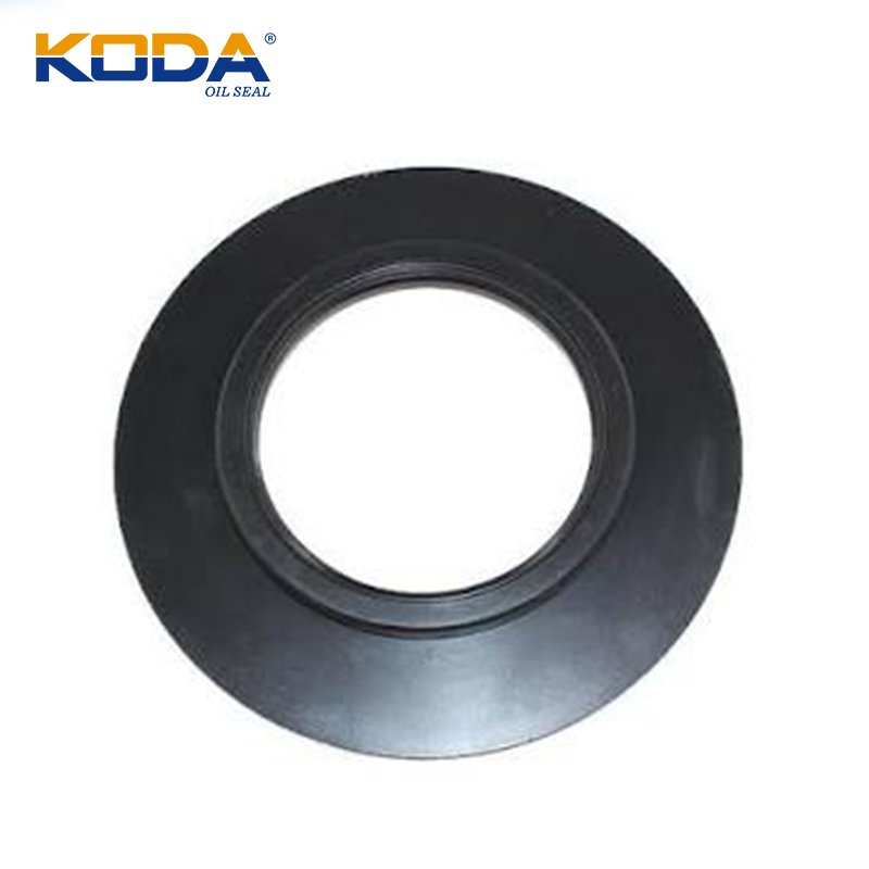
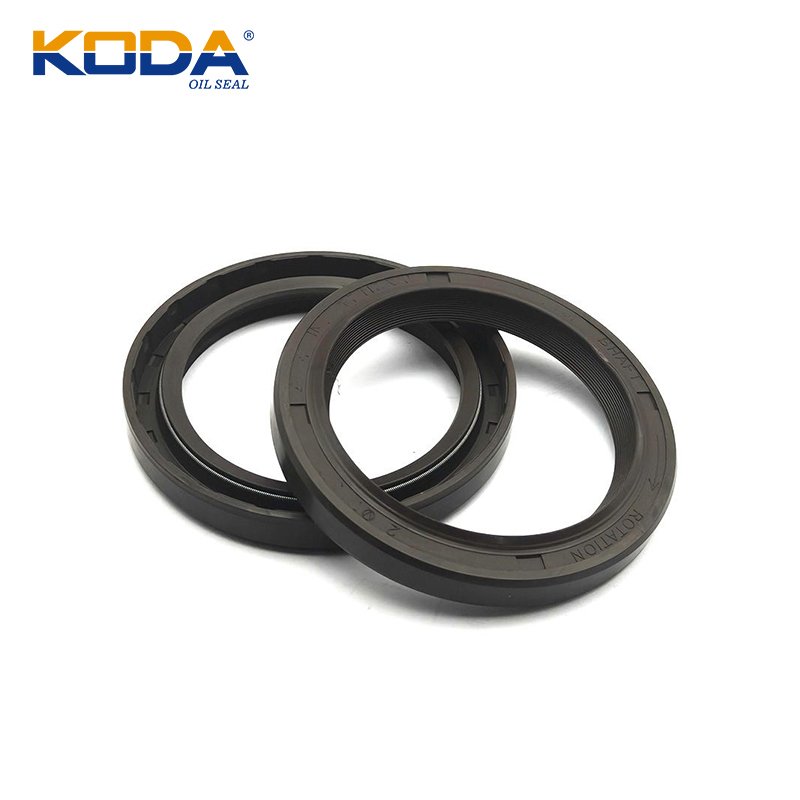
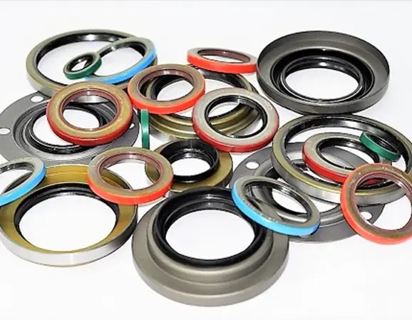
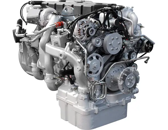
Perkins diesel engines are widely used in industrial equipment, agricultural machinery, construction equipment, generators, and other applications where dependable engine operation is essential. In these environments, an appropriately specified Perkins oil seal helps retain engine oil, protect rotating components, and reduce the risk of contamination that can accelerate wear or cause unexpected downtime.
Oil seals are precision-engineered components. Their performance depends on more than nominal diameter: shaft condition, housing dimensions, sealing-lip geometry, elastomer compatibility, rotational speed, temperature, and installation quality all influence service life. A replacement that looks similar to the original may still leak if its construction or operating limits are unsuitable.
If you have questions about PERKINS Oil Seal, please contact us!
Important selection advice: Identify the engine model and original part number before ordering. When a number is unavailable, combine dimensional measurements with the engine serial number, application details, and a verified parts-catalog reference. Do not rely on dimensions alone when selecting a critical engine seal.
SHOW MORE
Perkins Oil Seals for Diesel Engine Applications
A radial shaft oil seal creates a controlled contact interface between a rotating shaft and a stationary housing. Its primary purpose is to retain lubricant while helping prevent dust, moisture, and other contaminants from entering the assembly. In a diesel engine, the correct sealing component supports lubrication reliability and helps protect surrounding components from oil loss.
Perkins engines are installed in many types of equipment, and seal requirements vary by engine family, configuration, production specification, and sealing location. A seal suitable for one engine may not fit another, even if the engines share a similar displacement or application. Always verify the exact engine identification and the relevant parts documentation.
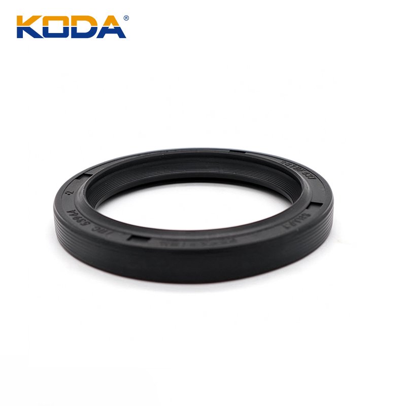
Front Crankshaft Oil Seals
Help control oil leakage at the front crankshaft and timing-cover area. Shaft finish, installation depth, and correct dimensions are important.
Rear Crankshaft Oil Seals
Help retain engine oil at the rear crankshaft. Some applications use specialized seal and housing assemblies requiring specific installation procedures.
Valve Stem Seals
Regulate the amount of oil passing along the valve stem to support appropriate valve-guide lubrication and help limit excessive oil consumption.
Other Engine Shaft Seals
Depending on the engine design, additional seals may be fitted to auxiliary drives or other rotating assemblies.
For engine-specific parts information, genuine replacement components, and service documentation, consult Perkins Parts and Service. Its authorized distributor network can help identify suitable components using the information for the particular engine.
Perkins Oil Seal Types and Their Functions
Although oil seals share the same basic purpose, their construction and sealing mechanisms can differ considerably. Understanding the type of seal fitted to an engine helps technicians and purchasers avoid incorrect substitutions and unnecessary rework.
Front Crankshaft Oil Seals
The front crankshaft seal is commonly installed around the crankshaft at the front of the engine, near the timing cover or front drive arrangement. It must maintain contact with the rotating shaft while accommodating the specified operating speed, temperature, and lubrication conditions.
A front crankshaft leak may be caused by a worn sealing lip, a damaged shaft contact area, incorrect installation, excessive shaft movement, or an unsuitable replacement. Oil leaking from nearby covers, joints, or other components can also be mistaken for a failed crankshaft seal. Cleaning the area and locating the actual source of the leak can prevent unnecessary dismantling.
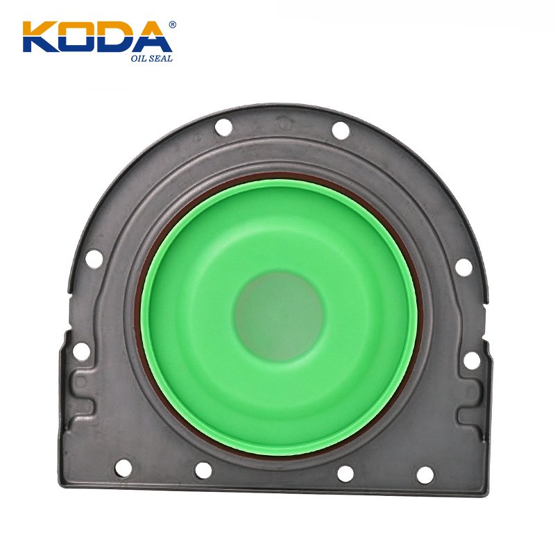
Rear Crankshaft Oil Seals
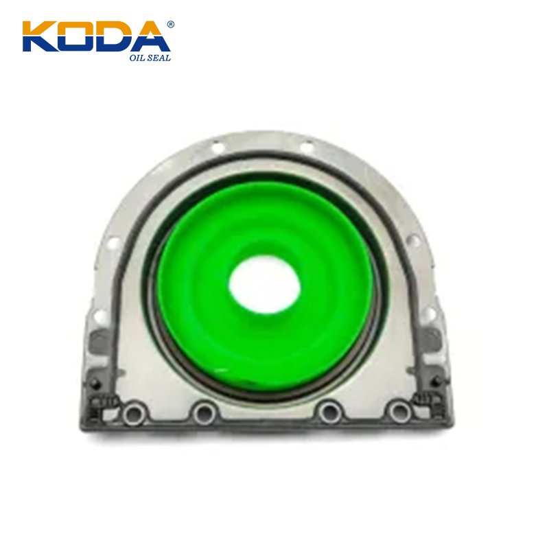
The rear crankshaft seal helps retain engine oil at the flywheel end of the crankshaft. Depending on the engine family, it may be a conventional elastomer lip seal, a specialized low-friction design, or part of a more complex sealing and housing arrangement.
Rear crankshaft seal replacement can involve substantial labor because access may require removal of the transmission, flywheel, or other components. Correct part identification is therefore particularly important. Confirm whether the replacement is supplied as an individual seal or as part of a complete assembly, and follow the engine-specific installation procedure.
Before installation, inspect the crankshaft sealing surface and check for wear, contamination, or damage. If the original seal has created a wear groove, replacing the seal without addressing the shaft surface may not provide a durable repair.
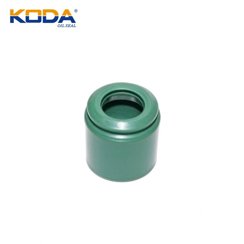
Valve Stem Seals
Valve stem seals control oil movement between the valve stem and guide area. They must allow the lubrication required by the valve-guide system while preventing excessive oil from entering the combustion chamber or exhaust path.
Worn valve stem seals can contribute to oil consumption and exhaust smoke, but these symptoms are not conclusive proof of seal failure. Worn valve guides, piston rings, cylinder wear, crankcase ventilation problems, and other engine faults can produce similar symptoms. Diagnosis should follow the relevant service procedure rather than relying on smoke color alone.
Valve stem seals are generally much smaller than crankshaft seals, and their dimensions and lip designs are application-specific. A replacement should be matched to the valve stem, guide arrangement, installation height, and required material specification.
Specialized and Housing-Integrated Seals
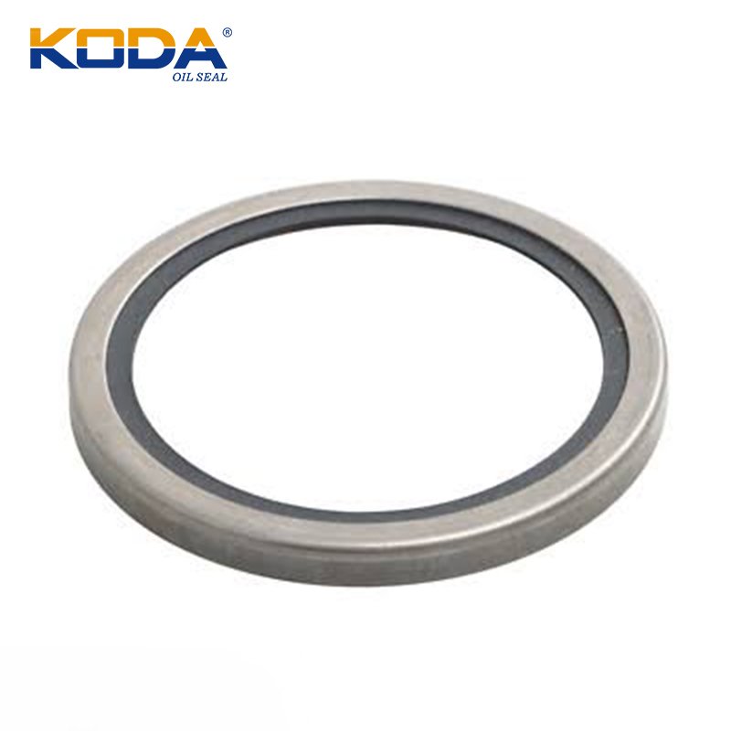
Some engine designs use seals integrated into housings or supplied with additional components. These products may have stepped dimensions, multiple sealing lips, molded profiles, or specific orientation requirements. A simple three-dimension comparison may not fully describe their geometry.
When a listing shows more than one width measurement, an unusual outside diameter, or an assembly reference, request a technical drawing or detailed specification. Confirm whether the supplier is offering a direct replacement for the original assembly or a different design that requires additional validation.
Perkins Oil Seal Part Numbers and Reference Dimensions
Part numbers and dimensional references can help narrow down replacement options. The examples below are drawn from the published Perkins oil seal product listing and related product pages. They are preliminary identification references, not a complete engine-to-seal compatibility chart.
| Listed part reference | Published dimensions | Application or verification notes |
|---|---|---|
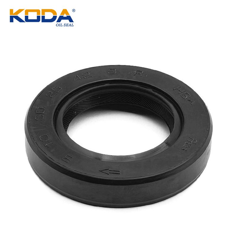
| 198636090 / 02/630092 / 02630092 | 25 × 42 × 8 mm | Listed as a front oil seal for Perkins 402D-05 and 402F-05 applications. Confirm the engine serial number and catalog reference. |
| 2418F436 | 60.33 × 79.4 × 9.52/11 mm | Listed with related CASE IH and Volvo references. Verify the complete profile and application before interchange. |
| 198636170 | 90 × 154 × 13 mm | Listed as a Perkins rear crankshaft seal. Confirm whether the engine requires a separate seal or a complete housing assembly. |
| 050209107 / 050209083 | 68 × 94/134 × 13 mm in the listing | Associated with Perkins 403A-11 and 403D-11 references. Clarify the stepped or alternative outside-diameter notation. |
| 82316553 / 12016553 | 9 × 13.4 × 15.9/13.85 mm | Listed as a valve stem seal with FPM material and related Perkins 2418M505 reference. Confirm the exact design. |
| 82316912 / 12016912 | 9 × 12.4/14.9 × 15 mm | Listed as a valve stem seal associated with Perkins 2418M507. Verify guide and stem dimensions. |
| 2418F437 / 02/100004 / 02/101435 | 60 × 80 × 9 mm | Listed as a front crankshaft oil seal with related engine references. Confirm the specific engine variant. |
| 143-8839 / 2418F475 | 133.35 × 158.75 × 12.63 mm | Listed for selected Perkins 1004 and 1006 engine references. Check the exact engine application and seal material. |
The dimensions and references above are taken from the Perkins oil seal product listing and its associated product information. Catalog data can use abbreviated measurements or list multiple related references. Always confirm the current specification with the supplier and the relevant Perkins parts information before ordering.
How to read seal dimensions: A conventional radial shaft seal is often described by inner diameter × outer diameter × width. A notation such as 9 × 13.4 × 15.9/13.85 or 68 × 94/134 × 13 may indicate a stepped profile, alternative diameter, or more complex geometry. Do not assume the slash-separated values are interchangeable dimensions; ask for a drawing or measurement explanation.
How to Select the Correct Perkins Replacement Oil Seal
A reliable replacement decision combines part-number identification, dimensional verification, material selection, and an understanding of the engine’s operating environment. This process is particularly important for equipment that operates for long periods or is difficult to access for repairs.
1. Identify the Engine and Original Part Number
Begin with the engine model and serial number. Use the applicable Perkins parts book, authorized distributor, or service documentation to identify the original seal. Record the complete part number, including prefixes, suffixes, and any superseding reference.
A cross-reference can help locate an aftermarket equivalent, but the number should be verified against reliable catalog data. Two part numbers that appear related may apply to different engine variants, production periods, or seal constructions. Where a part number has been superseded, confirm that the newer component is approved for the original application.
The official Perkins Parts and Service portal provides access to genuine parts support, distributor assistance, and engine-related information. This is a more reliable starting point than choosing a part solely from a general online search result.
2. Measure the Seal and Mating Surfaces
If the original number cannot be identified, measure the removed seal and, where possible, the shaft and housing. Use appropriate measuring tools and record the values in a consistent unit system.
Inner Diameter (ID)
Usually relates to the shaft diameter and the required sealing-lip interference.
Outer Diameter (OD)
Relates to the housing bore and the required outside fit.
Width or Profile Height
Must match the specified installation space and seal construction.
Measurements from a worn seal should be treated with care because deformation, wear, and damage can alter its shape. For specialized crankshaft seals and valve stem seals, the profile and installation height may be just as important as the nominal diameters. Request a technical drawing when the geometry is unclear.
3. Choose a Compatible Seal Material
Seal materials must tolerate the engine lubricant, operating temperature, contact conditions, and expected service environment. Material selection should follow the original specification or an engineering assessment of the application, rather than appearance or a generic description of rubber quality.
| Material family | Typical characteristics | Selection checks |
|---|---|---|
| NBR (nitrile rubber) | Commonly used for many petroleum-based oil-sealing applications. | Verify the compound’s temperature range, oil compatibility, hardness, and wear resistance. |
| HNBR | Can provide improved heat, aging, and mechanical properties compared with many conventional NBR compounds. | Confirm suitability for the specific lubricant and operating conditions. |
| FKM / FPM (fluoroelastomer) | Often selected for applications requiring particular heat and chemical resistance. | Check low-temperature flexibility and compatibility of the exact compound with the engine fluid. |
| PTFE-based designs | Used in certain specialized seals where low friction or specific operating characteristics are required. | Verify the shaft finish, installation method, and whether the design requires a special fitting procedure. |
These material descriptions are general engineering guidance and do not establish suitability for a specific Perkins engine. Different compounds within the same material family can have different performance limits. For a replacement decision, use the original equipment specification and technical data from the seal manufacturer.
For further engineering guidance on rotary shaft seals, consult the Parker Oil Seals Engineering Design Guide. It discusses shaft recommendations, housing conditions, and other factors that influence sealing performance. The final selection must still be checked against the actual Perkins application and seal design.
4. Consider Speed, Temperature, and Operating Conditions
The operating speed and temperature of a shaft influence friction and heat at the seal lip. Poor lubrication, excessive shaft runout, contamination, or a material that is unsuitable for the operating environment can accelerate wear. The same seal design may perform differently in a stationary generator, an agricultural machine, and equipment that experiences frequent load changes.
Consider cold starts as well as normal operating temperature, and verify the actual lubricant used in the engine. If the equipment operates in dusty, wet, or high-temperature environments, check whether the original design includes a secondary lip, protective element, or other feature intended for those conditions.
Common Causes of Perkins Oil Seal Leakage
An oil leak around a Perkins engine can result from seal wear, installation damage, incorrect replacement parts, shaft deterioration, or problems elsewhere in the engine. Identifying the cause before replacing the seal helps prevent repeat failures and reduces unnecessary repair work.
Incorrect Part Number or Seal Dimensions
An incorrect inner diameter can produce inadequate or excessive lip interference. An unsuitable outer diameter may compromise housing retention, while an incorrect width can prevent the seal from reaching the prescribed position. Differences in lip profile or case construction can also affect performance.
Before installation, compare the replacement against the original part number and specification. If a cross-reference is used, confirm that it is supported by reliable application data and not merely by a similar appearance or approximate measurement.
Worn or Damaged Shaft Surface
A seal lip needs a suitable mating surface to maintain an effective sealing interface. Grooves, scratches, corrosion, burrs, and excessive roughness can create a leakage path or accelerate wear. A new seal may therefore leak quickly if the shaft contact area is damaged.
Inspect the shaft during disassembly and compare its condition with the relevant service requirements. Where a wear groove is present, use an approved repair method or replace the damaged component as specified. A new seal should not be expected to correct a shaft surface that falls outside the acceptable limits.
Installation Errors
The sealing lip can be cut when it passes over a sharp edge, keyway, thread, or damaged shaft surface. Uneven pressing can distort the seal, while incorrect orientation or installation depth can prevent it from operating as designed.
Use the specified installation tool, protect the lip during assembly, and follow the correct orientation and depth. Specialized seals may require particular handling or preparation, so always refer to the product instructions and the engine service documentation.
Excessive Shaft Movement or Mechanical Wear
Worn bearings, misalignment, or excessive shaft runout can prevent the sealing lip from maintaining consistent contact. If the shaft moves beyond the seal’s design capability, replacing the seal alone may not resolve the leakage.
Inspect the relevant bearing arrangement, shaft movement, and clearances according to the applicable service procedure. Correct the underlying mechanical issue before installing a new seal.
Excessive Crankcase Pressure or Other Engine Faults
Abnormal crankcase pressure, a restricted ventilation system, or another engine fault can contribute to oil leakage at sealing points. If a new crankshaft seal continues to leak, investigate the surrounding engine system rather than assuming the replacement part is defective.
Similarly, oil found near a crankshaft seal may originate from a nearby gasket, housing joint, or other component. Clean the affected area and determine the true source before undertaking major disassembly.
Maintenance principle: Diagnose the leak, inspect the shaft and housing, verify the replacement specification, and correct the root cause. Repeated seal replacement without checking the complete system can increase labor costs without delivering a lasting repair.
Installation Guidelines for Perkins Replacement Oil Seals
Correct installation helps preserve the sealing lip and ensures that the seal operates within its intended design conditions. The procedure varies by seal type, so the following recommendations should be used alongside the specific Perkins workshop instructions.
Prepare the Components
Clean the shaft and housing, and remove contamination that could damage the sealing interface. Inspect the shaft contact surface, housing bore, and any chamfers or lead-in features. Check for burrs, corrosion, scoring, and dimensional damage before installing the replacement.
Examine the new seal for visible cuts, deformation, damaged lips, or other defects. Keep it clean and protected until assembly. If the seal has a specified installation orientation, identify that orientation before beginning the work.
Install Without Damaging the Lip
Use an appropriate driver or installation sleeve to apply force evenly. Protect the lip when the seal passes over splines, keyways, or other sharp features. Avoid direct impacts on the flexible lip and do not force a seal into a housing when the fit or alignment appears incorrect.
Follow the manufacturer’s instructions for lubrication before installation. Some seals require a compatible lubricant on the lip, while specialized low-friction designs may have different requirements. Do not assume that every seal should be installed using the same method.
Verify Position and Reassemble Correctly
Check that the seal is seated evenly and at the specified depth. Reassemble the surrounding components according to the engine service procedure, and restore the correct lubricant level and type. Follow all applicable torque, adjustment, and inspection requirements for the components removed during the repair.
After the engine returns to operation, inspect the repair area for leakage and abnormal conditions. If the leak persists, investigate the cause rather than immediately installing another seal. For specialized rear crankshaft seals and valve stem seals, use the exact engine-specific procedure because access, handling, and installation requirements can differ significantly.
Quality Requirements for Perkins Oil Seal Suppliers
For equipment owners, repair workshops, distributors, and parts wholesalers, supplier selection should consider application accuracy, product consistency, and technical support as well as price. An inexpensive seal can become a costly choice if it causes repeat labor, downtime, or damage to the surrounding assembly.
Application Verification
Look for clear part-number references, dimensional drawings, and confirmation of the intended engine application.
Material Control
Ask about the specified elastomer or polymer, material consistency, and supporting technical documentation where required.
Dimensional Inspection
Confirm that critical dimensions and sealing features are checked against the agreed product specification.
Traceability and Support
Review batch identification, packaging, delivery commitments, and the process for resolving fitment concerns.
When purchasing aftermarket products, clarify whether the part is a genuine Perkins component, a branded aftermarket replacement, or an independently manufactured equivalent. These categories should be represented accurately. A supplier’s quality certification can provide useful information about its management system, but it does not independently prove that a particular seal fits a specific engine.
For genuine components and engine-specific parts support, consult Perkins Parts and Service. For technical details, use the parts book and service literature applicable to the exact engine model and serial number.
Manufacturing and Quality Inspection Considerations
A reliable oil seal manufacturing process requires control over material preparation, tooling, forming or molding, finishing, and inspection. The specific process depends on the design, including whether the seal incorporates an elastomer lip, metal case, garter spring, PTFE element, or an integrated housing.
Critical characteristics may include inner and outer diameters, width, lip geometry, case concentricity, spring retention where applicable, and surface condition. The manufacturer should define the relevant characteristics in a technical specification and use appropriate inspection methods to verify conformity.
For custom or non-standard replacement seals, provide a sample or drawing, original reference numbers, expected quantity, operating conditions, and material requirements. Before production, clarify tolerances, inspection criteria, packaging, and whether the proposed design is a direct replacement or requires additional engineering validation.
The Parker Oil Seals Engineering Design Guide provides useful technical background on shaft material, shaft finish, housing geometry, and dimensional tolerances. Its recommendations should be applied in conjunction with the requirements of the actual Perkins engine and the specific seal construction.
Storage and Handling of Perkins Oil Seals
Oil seals should be kept in clean, dry storage and protected from direct sunlight, excessive heat, ozone sources, dust, and incompatible chemicals. Keep the original packaging intact until the seal is required, and avoid stretching, bending, or compressing flexible lips during handling.
Storage requirements vary by elastomer and seal construction. Follow the manufacturer’s guidance for storage conditions and shelf life rather than assuming a universal storage period. Inspect products before installation for cracking, deformation, corrosion, or other signs of deterioration.
For workshops and distributors managing multiple engine families, organize stock by part number and application. Maintain batch identification where available, rotate inventory according to supplier recommendations, and keep similar-looking seals clearly separated. These practices reduce the risk of fitting an incorrect or deteriorated part during maintenance.
Perkins oil seal purchasing checklist
✓ Engine model and serial number
✓ Original part number or verified replacement reference
✓ Confirmed dimensions, profile, and installation requirements
✓ Material compatibility with the specified engine lubricant and temperature
✓ Supplier confirmation, inspection documentation, and delivery requirements
Frequently Asked Questions About Perkins Oil Seals
1. How do I find the correct oil seal for a Perkins engine?
Identify the engine model and serial number, then check the applicable Perkins parts information or consult an authorized distributor. If the original part number is unavailable, provide the application, seal dimensions, and any readable markings to a qualified supplier. Confirm the exact fit before ordering.
2. Can I replace a Perkins oil seal using only its dimensions?
Dimensions are useful for preliminary identification, but they are not always sufficient. The replacement must also match the sealing profile, material, installation depth, and operating requirements. Specialized rear crankshaft seals and valve stem seals may require additional design information.
3. Which material is best for Perkins oil seals?
The best material depends on the engine’s lubricant, operating temperature, shaft speed, and original equipment specification. NBR is commonly used in many oil-sealing applications, while HNBR, FKM, or PTFE-based designs may be suitable for specific requirements. Verify the exact material or compound before choosing a replacement.
4. Why does a new Perkins oil seal continue to leak?
Possible causes include an incorrect part, damaged sealing lip, worn shaft surface, excessive shaft movement, incorrect installation, or a problem elsewhere in the engine. Inspect the complete assembly and determine the source of the leak before replacing the seal again.
5. What information should I provide when requesting a Perkins oil seal quotation?
Provide the engine model, serial number, original part number, required quantity, and application. If possible, include the dimensions, a drawing or photographs of the old seal, and any material or operating requirements. Ask the supplier to confirm compatibility, lead time, and available quality documentation.
 Quick View
143-8839 2418F475 Rear Crank Shaft Seal For Perkins 1006 135TI 4.41
PERKINS Oil Seal- Quick View
Front crankshaft oil seals 2415344 1447689M1 133566 295810M1
PERKINS Oil Seal - Quick View
2418F437 Front Oil Seal Perkins 60×80×9 Engine Part Seal
PERKINS Oil Seal - Quick View
3084879 For Cummins Thermostat Seal
PERKINS Oil Seal - Quick View
2418F704 crankshaft seal rear suitable for PERKINS
PERKINS Oil Seal - Quick View
- Quick View
Valve Stem Seal 82316553 12016553 For PERKINS 2418M505 VOLVO 3976841
PERKINS Oil Seal - Quick View
- Quick View
Perkins 198636170 Rear Crankshaft Seal Engine Part 90×154×13
PERKINS Oil Seal - Quick View
Crankshaft Oil Seal CASE IH 073020 PERKINS 2418F436 VOLVO 6613348
PERKINS Oil Seal - Quick View
- Quick View
232-7449 Perkins Crankshaft Seal 2418F704 4224762M1
PERKINS Oil Seal