
Understanding O-Ring Durometer Scales and Why They Matter
O-ring performance depends on far more than nominal size and polymer family. One of the most important material specifications is hardness, commonly expressed as Shore A durometer. When engineers specify an O-ring as 70 Shore A, 80 Shore A, or 90 Shore A, they are defining a measurable indentation-hardness characteristic that influences how readily the elastomer deforms, fills surface irregularities, resists extrusion, and responds to installation forces.
Understanding O-Ring Durometer is therefore essential when selecting seals for hydraulic equipment, pneumatic systems, automotive components, industrial machinery, pumps, valves, cylinders, agricultural equipment, and other demanding applications. The hardness number is useful, but it should never be treated as a complete description of sealing performance. Two compounds can have the same nominal Shore A hardness while exhibiting substantially different resistance to chemicals, temperature, compression set, abrasion, swelling, and dynamic wear.
This article explains the engineering principles behind durometer scales, the differences between Shore A and other scales, relevant ASTM and ISO standards, practical material comparisons, testing considerations, installation effects, failure mechanisms, and a systematic method for choosing the correct hardness for an O-ring application.
◆ Engineering takeaway: Durometer is an indentation-hardness measurement, not a direct measurement of tensile strength, pressure capability, modulus, chemical resistance, or service life. A reliable O-ring specification must combine hardness with compound, temperature, pressure, geometry, fluid compatibility, surface finish, installation conditions, and dynamic motion.
What Is O-Ring Durometer?
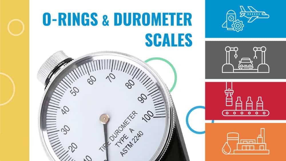
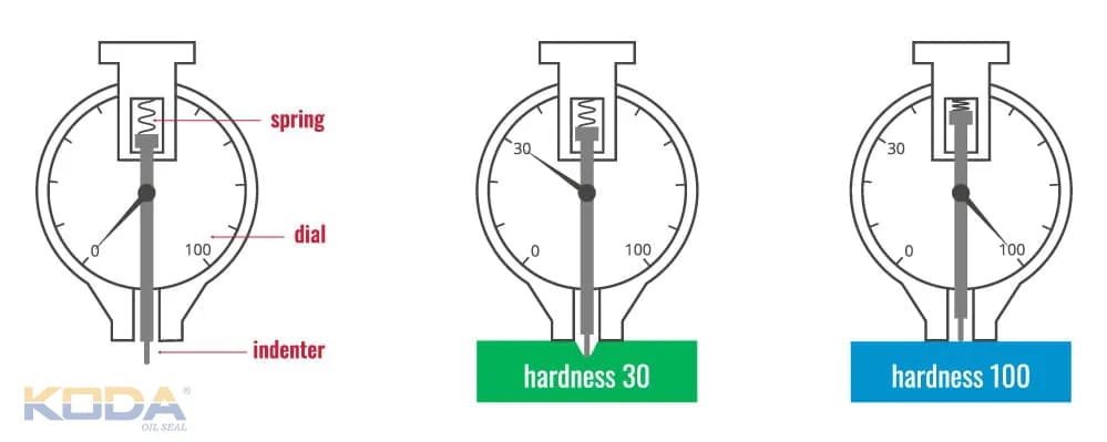
Durometer describes the resistance of an elastomeric material to penetration by a standardized indenter. In simple terms, a harder rubber produces less indentation under the specified test conditions, while a softer rubber allows greater indentation.
The measurement is particularly useful for elastomers because conventional metal hardness methods do not adequately characterize rubber-like materials. ASTM D2240 defines procedures for measuring rubber and related materials with several durometer types, while ISO 48-4:2018 specifies indentation hardness by the durometer method for vulcanized or thermoplastic rubber. ISO identifies Shore A for normal-hardness rubber, Shore D for high-hardness materials, Shore AO for low-hardness and cellular materials, and Shore AM for thin rubber specimens.
For most conventional O-rings, Shore A is the scale engineers encounter most frequently. Typical sealing compounds are commonly supplied in ranges such as approximately 60, 70, 75, 80, or 90 Shore A, although exact available grades depend on the elastomer, compound formulation, manufacturer, and application.
A higher Shore A value generally indicates a stiffer material under the particular indentation test. However, the relationship between hardness and other mechanical properties is not one-to-one. ASTM specifically notes that indentation hardness depends on material behavior, indenter geometry, and applied force, and that there is no simple universal conversion between different durometer types.
Shore A, Shore D, Shore OO, and Other Durometer Scales
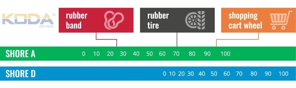
The term “durometer” does not refer to only one scale. Different scales use different indenter geometries and test forces and are intended for different hardness ranges. Consequently, a Shore A value must not be casually converted into a Shore D value as though the two scales were interchangeable.
| Scale | Typical Use | Relevance to Seals |
|---|---|---|
| Shore A | Normal-hardness rubber and elastomers | Primary scale for many O-rings |
| Shore D | Hard rubber and harder polymers | Useful when the compound is beyond normal Shore A range |
| Shore OO | Very soft elastomers and flexible materials | Relevant to exceptionally soft sealing materials |
| Shore O | Soft elastomeric materials | Less common for conventional industrial O-rings |
| Shore AM | Thin rubber specimens | Important when specimen geometry is thin |
ISO 48-4 specifically distinguishes Shore A, D, AO, and AM according to material hardness range and specimen conditions. This is important because the same material can produce different measured behavior when test scale, geometry, force, temperature, and dwell conditions change.
Why O-Ring Hardness Influences Sealing Performance
An O-ring seals by generating contact pressure against mating surfaces. In a static application, the elastomer is normally compressed inside a groove. The material attempts to recover elastically and maintain contact against the gland surfaces.
A softer compound generally conforms more readily to small surface imperfections. This can be advantageous when sealing relatively rough surfaces or when installation requires low assembly force. However, softness can become a disadvantage when pressure, extrusion clearance, abrasion, or mechanical deformation becomes severe.
A harder compound generally provides greater resistance to deformation and can improve resistance to extrusion in appropriately designed high-pressure systems. The trade-off is that installation may require greater force, the material may be less forgiving of surface defects, and dynamic friction may increase depending on the compound and lubrication system.
⚠ Important: Do not select a 90 Shore A O-ring simply because the application has high pressure. Pressure capability depends on gland geometry, extrusion gap, temperature, material strength, anti-extrusion devices, pressure cycling, and the actual elastomer compound.
Common O-Ring Hardness Options
For many industrial sealing applications, 70 Shore A is a widely used starting point because it provides a practical balance between conformability, mechanical strength, installation behavior, and general sealing performance. This does not mean 70 Shore A is universally correct.
| Approximate Hardness | General Characteristics | Typical Consideration |
|---|---|---|
| 60 Shore A | Relatively soft and conformable | Low assembly force and good conformity; pressure and extrusion design require attention |
| 70 Shore A | Balanced stiffness | Common general-purpose sealing range |
| 80 Shore A | Stiffer and more deformation-resistant | Useful where additional resistance to extrusion or mechanical deformation is required |
| 90 Shore A | High stiffness within Shore A range | High-pressure or mechanically demanding designs when geometry and compound support it |
These ranges are engineering-oriented examples rather than universal material classifications. The correct hardness must be verified against the specific seal compound and application requirements.
Durometer Does Not Equal Tensile Strength
One of the most common mistakes in O-ring selection is assuming that a harder material automatically has higher tensile strength or longer life. Elastomer formulations contain different polymers, fillers, plasticizers, curing systems, pigments, and reinforcing agents. These ingredients can change hardness and other mechanical properties independently.
For example, an NBR compound and an FKM compound may both be specified at 75 Shore A, yet their resistance to fuels, oils, elevated temperatures, ozone, and particular chemicals can be very different. Likewise, two 70 Shore A NBR compounds can have different compression set and abrasion performance because their formulations and cure systems differ.
For that reason, an engineering specification should preferably identify the polymer family, compound designation where required, hardness, dimensional standard, temperature range, fluid compatibility, and relevant performance requirements.
O-Ring Material Selection and Hardness
Hardness should be selected after the chemical and thermal environment has been established. Common O-ring materials include NBR, HNBR, EPDM, FKM, FFKM, silicone, and polyurethane. Each material has different strengths and limitations.
| Material | Typical Strength | Potential Limitation |
|---|---|---|
| NBR | Good resistance to many petroleum oils and fuels; economical | Limited resistance to ozone and some aggressive chemicals |
| HNBR | Improved heat, mechanical, and ozone performance compared with conventional NBR grades | Higher material cost and application-specific compatibility |
| EPDM | Strong resistance to hot water, steam in suitable grades, weathering, and ozone | Generally unsuitable for many petroleum-oil applications |
| FKM | Excellent high-temperature and broad chemical resistance in many applications | Low-temperature flexibility and compatibility must be evaluated |
| Silicone | Wide temperature capability and excellent flexibility | Lower tear and abrasion resistance in many grades |
| FFKM | Exceptional chemical and high-temperature resistance in specialized grades | Very high cost; compound-specific limitations remain |
The hardness selected within each material family should be treated as a design variable rather than a substitute for chemical compatibility testing. Engineers should consult compound-specific compatibility charts and, where necessary, perform immersion, compression-set, tensile, aging, or application-specific testing.
How Temperature Changes Durometer Behavior
Elastomers are viscoelastic materials, meaning their response depends on both temperature and time. As temperature increases, many elastomers become softer and more compliant. As temperature decreases, many elastomers become stiffer and less flexible.
This means a Shore A value measured at laboratory ambient conditions should not be interpreted as a constant mechanical state across the entire service temperature range.
For example, an O-ring specified at 70 Shore A may behave significantly differently at a low-temperature startup condition than it does at room temperature. Similarly, prolonged exposure to elevated temperature can alter the polymer through aging, oxidation, plasticizer loss, crosslink changes, or other mechanisms, depending on the material.
◆ Expert tip: If an O-ring operates across a wide temperature range, evaluate compression set, low-temperature flexibility, high-temperature aging, and fluid compatibility rather than relying solely on the original room-temperature Shore A value.
Hardness and Compression Force
O-rings are normally compressed in their glands to establish initial sealing contact. The required assembly force is influenced by cross-section, squeeze, material stiffness, surface finish, lubrication, temperature, and friction.
As a simplified engineering concept, increasing material hardness often increases the force required to deform the O-ring. However, a direct universal formula such as “70 Shore A requires X newtons” is not valid because Shore A hardness is not equivalent to a single elastic modulus.
For preliminary design, engineers may evaluate gland squeeze as:
Squeeze (%) = (O-ring cross-section − gland gap height) ÷ O-ring cross-section × 100
For example, if a nominal 3.00 mm cross-section O-ring is installed into a groove providing 2.40 mm available height, the nominal squeeze is approximately (3.00 − 2.40) / 3.00 × 100 = 20%.
The appropriate squeeze depends on whether the application is static, reciprocating, oscillating, or rotary, as well as the seal material and gland design. Excessive squeeze can increase friction and accelerate wear, while insufficient squeeze can reduce sealing reliability.
Hardness and Pressure Resistance
Pressure can force an elastomer into the clearance gap between mating components. This phenomenon is commonly referred to as extrusion. The risk becomes more significant as pressure increases, clearance grows, temperature rises, or material strength decreases.
A harder O-ring can offer greater resistance to deformation, but hardness alone does not determine extrusion resistance. A properly selected backup ring, reduced extrusion gap, suitable groove geometry, and a compound with appropriate tensile and tear properties can be more important than simply increasing Shore A hardness.
| Design Variable | Potential Effect on Extrusion |
|---|---|
| Higher pressure | Generally increases extrusion force |
| Larger clearance gap | Increases available space for material to enter |
| Higher temperature | Can reduce elastomer stiffness and increase deformation |
| Higher hardness | Can improve resistance to deformation, subject to compound properties |
| Backup ring | Can substantially reduce extrusion risk in suitable high-pressure designs |
ASTM D2240 and ISO 48-4 Testing
ASTM D2240 is a widely referenced method for durometer hardness testing. The standard describes multiple durometer types and emphasizes that hardness measurements depend on the specific instrument and test conditions.
ISO 48-4:2018 provides an international method for Shore indentation hardness. ISO confirms that the standard remains current following its systematic review.
In production quality control, it is important to specify the applicable standard, hardness scale, test method, specimen requirements, conditioning, measurement location, and acceptance tolerance. Otherwise, two laboratories may report apparently different values even when testing similar material.
Why Durometer Measurements Can Vary
Durometer testing looks simple, but reliable measurement requires controlled conditions. ASTM notes that indentation hardness depends on the indenter and applied force as well as the elastic and viscoelastic behavior of the material.
Common variables include specimen thickness, surface flatness, temperature, material conditioning, test location, instrument calibration, applied force, dwell time, and operator technique.
Thin O-rings are particularly challenging because the substrate beneath the elastomer can influence the measured indentation. A measurement made directly on a thin cross-section should therefore not automatically be compared with a measurement made on a thick standardized slab.
Laboratory Test Example
The following is an illustrative laboratory test example, not a report of actual customer testing or a manufacturer’s production dataset. Consider three elastomer batches specified nominally at 70 Shore A. A laboratory could condition representative specimens under a controlled environment, verify the instrument against suitable reference materials, make measurements at defined locations, and calculate an average together with the observed range.
| Illustrative Batch | Nominal Specification | Illustrative Measurements |
|---|---|---|
| A | 70 Shore A | Example: 69, 70, 71, 70, 69 |
| B | 70 Shore A | Example: 66, 68, 70, 69, 67 |
| C | 70 Shore A | Example: 71, 72, 73, 72, 71 |
These values are deliberately presented as hypothetical examples. They do not represent certified product data, customer data, factory data, or guaranteed acceptance limits. The purpose is to demonstrate why an engineer should evaluate measurement distribution rather than relying on a single hardness reading.
Hardness, Thermal Conductivity, and Heat Transfer
Hardness and thermal conductivity are separate material properties. Increasing an O-ring’s Shore A hardness does not provide a reliable method for predicting its thermal conductivity.
Elastomers generally have relatively low thermal conductivity compared with metals, which means heat transfer through an O-ring is strongly influenced by the surrounding housing, fluid, contact geometry, and temperature gradients. Exact thermal conductivity values vary substantially by polymer, fillers, compound formulation, temperature, and measurement method.
For thermal design, engineers should obtain compound-specific thermal data rather than assigning a conductivity value based solely on hardness.
Chemical Resistance Cannot Be Predicted from Durometer
A common misconception is that a harder O-ring is automatically more chemically resistant. This is incorrect. Chemical resistance is predominantly related to polymer chemistry, formulation, crosslinking, additives, temperature, concentration, exposure time, and fluid composition.
For example, an EPDM O-ring may be an excellent choice for certain water-based applications but inappropriate for petroleum oils. FKM is often selected for demanding oil and fuel environments, but its suitability must still be checked against the specific chemical and temperature conditions.
Chemical exposure can cause swelling, shrinkage, softening, hardening, cracking, extraction of additives, loss of tensile properties, or permanent deformation. A post-exposure hardness measurement can therefore be useful as one part of a failure investigation.
Hardness and Compression Set
Compression set is another property that must not be confused with hardness. Compression set describes the tendency of an elastomer to retain deformation after prolonged compression under specified conditions.
An O-ring can have an appropriate Shore A hardness yet exhibit unacceptable compression set because of unsuitable compound chemistry, excessive temperature, inadequate formulation, aging, or incompatible service conditions.
For long-term static sealing, compression-set performance can be much more important than a small difference between, for example, two nearby hardness grades.
Case Example: Selecting Hardness for a Hydraulic Seal
This is an engineering case example created for illustration. It does not represent a disclosed customer, proprietary project, or verified field-service record.
Imagine a hydraulic manifold using an O-ring in a static connection. The system experiences pressure cycling, moderate temperature variation, and a machined metal-to-metal joint. An initial design uses a 70 Shore A compound.
During design review, engineers identify a relatively large clearance condition and pressure pulses. Instead of immediately switching to a harder O-ring, they evaluate the entire sealing system: gland dimensions, extrusion clearance, material tensile and tear performance, squeeze, temperature, surface finish, and the possibility of a backup ring.
The engineering conclusion could be that improving gland geometry and controlling extrusion clearance provides more robust protection than simply changing from 70 to 90 Shore A. If a harder compound is selected, assembly force and compatibility must also be reassessed.
Lesson: The best seal design solves the system problem rather than optimizing a single specification number.
Failure Mode Analysis: What Happens When Hardness Is Wrong?
1. Excessively soft material: The O-ring may deform more easily during installation or under pressure. In a poorly controlled extrusion gap, the material can be forced into the clearance and eventually develop nibbling or extrusion damage.
2. Excessively hard material: The O-ring may require greater installation force and may have reduced ability to accommodate surface irregularities. In dynamic applications, increased friction may contribute to heat generation and wear.
3. Incorrect hardness measurement: A thin cross-section, poor calibration, inappropriate scale, contaminated surface, or inconsistent test conditions can produce misleading results.
4. Correct hardness but wrong compound: The seal may fail through swelling, chemical attack, thermal degradation, or compression set even though its measured hardness is within specification.
5. Correct material but incorrect gland: Excessive clearance, insufficient squeeze, sharp edges, poor surface finish, or inadequate lead-in geometry can cause premature failure regardless of nominal hardness.
Common O-Ring Failure Patterns
| Failure Appearance | Possible Cause | Investigation Direction |
|---|---|---|
| Nibbled or torn edge | Extrusion, excessive clearance, damaged installation | Check pressure, gap, hardness, backup ring, and gland geometry |
| Flattened cross-section | Excessive squeeze or long-term compression | Inspect gland dimensions and compression set |
| Cracks | Ozone, aging, thermal degradation, incompatible environment | Review material chemistry and environmental exposure |
| Swelling | Fluid incompatibility | Conduct controlled immersion and dimensional change testing |
| Worn surface | Dynamic friction, poor lubrication, rough shaft, unsuitable material | Check surface finish, speed, temperature, lubrication, and compound |
How to Choose the Correct O-Ring Durometer
A practical selection process should begin with the application rather than the hardness number.
Step 1 — Identify the fluid. Determine whether the seal contacts hydraulic oil, mineral oil, fuel, water, steam, refrigerant, cleaning chemicals, food-processing fluids, or another medium.
Step 2 — Establish temperature. Record minimum, normal, maximum, transient, and startup temperatures.
Step 3 — Determine pressure. Include operating pressure, peak pressure, pressure cycling, vacuum conditions, and differential pressure.
Step 4 — Determine motion. Static, reciprocating, oscillating, and rotary applications impose different friction and wear demands.
Step 5 — Check gland geometry. Verify squeeze, fill, clearance, extrusion risk, corner radius, and installation geometry.
Step 6 — Select material. Choose the polymer and compound based on chemical and thermal requirements.
Step 7 — Select hardness. Choose the Shore A grade that provides an appropriate balance of conformity, extrusion resistance, friction, assembly force, and mechanical performance.
Step 8 — Validate. For critical applications, conduct application-specific testing instead of relying only on catalog data.
Installation Practices for Different O-Ring Hardnesses
Installation quality can have a greater effect on seal reliability than a small difference in nominal hardness. Before installation, the gland should be clean, free of burrs, and properly inspected.
Sharp edges can cut softer O-rings during assembly. Excessive stretching can reduce the effective cross-section in some applications. Twisting can create localized stress concentrations and may lead to spiral failure in reciprocating service.
Appropriate compatible lubrication can reduce installation damage and friction, but the lubricant itself must be compatible with both the elastomer and the process fluid.
For higher-hardness compounds, assembly tooling and lead-in geometry become especially important because the material may be less forgiving during installation.
Surface Finish and Durometer Selection
An O-ring must maintain intimate contact with its mating surfaces. Surface roughness, machining marks, scratches, porosity, and damage can create leakage paths.
A softer material may conform better to minor irregularities, but it cannot compensate indefinitely for a damaged sealing surface. Conversely, a harder compound may provide excellent mechanical stability but be less capable of conforming to deep or unfavorable surface features.
Surface finish should therefore be specified according to the seal type, motion, fluid, pressure, and manufacturer or applicable engineering standard rather than selected solely according to Shore A hardness.
Hardness Tolerance and Quality Control
When an O-ring is specified at a nominal hardness, the acceptable tolerance should be clearly defined by the applicable material specification, drawing, purchase specification, or manufacturer documentation.
A production quality-control program may monitor incoming compound, cured sheets, molded samples, and finished components. The testing method should remain consistent so that changes in instrument, specimen geometry, operator technique, or conditioning do not create false trends.
For critical applications, hardness should be considered alongside tensile strength, elongation, compression set, heat aging, fluid immersion, dimensional inspection, and visual examination.
O-Ring Durometer and Dynamic Applications
Dynamic seals experience friction, heat generation, wear, and repeated deformation. A hardness change that seems beneficial for static pressure resistance can produce undesirable friction or wear in a reciprocating or rotary application.
Dynamic performance also depends on lubrication, surface velocity, counterface finish, pressure, temperature, seal geometry, and elastomer viscoelasticity.
For this reason, engineers should avoid choosing a very hard O-ring simply because the application is mechanically demanding. A balanced compound and geometry can outperform a harder material in actual service.
A Practical Durometer Selection Matrix
| Application Condition | Potential Starting Direction | Main Verification |
|---|---|---|
| General static sealing | Medium Shore A range | Compression, fluid compatibility, temperature |
| High-pressure static sealing | Medium-to-higher hardness may be considered | Extrusion gap, backup ring, tensile/tear properties |
| Low-pressure pneumatic sealing | Conformable material may be beneficial | Friction, leakage, compression, lubrication |
| Reciprocating service | Application-specific hardness | Friction, wear, speed, lubrication, surface finish |
| Chemical service | Select polymer first, hardness second | Immersion, swelling, hardness change, tensile retention |
How to Read an O-Ring Specification Correctly
A robust specification might identify the O-ring size standard, material family, hardness, applicable material specification, temperature range, fluid compatibility, and special requirements.
For example, a simplified engineering description could specify an O-ring according to its dimensional standard, an NBR or FKM compound, a nominal hardness such as 70 Shore A, and additional requirements for compression set or fluid resistance.
A statement such as “rubber O-ring, 70 hardness” is insufficient for many industrial applications because it leaves the polymer family, compound formulation, dimensions, tolerance, temperature capability, and fluid compatibility undefined.
For engineers comparing available products, detailed O-Ring Durometer information can help establish whether the quoted hardness and test method match the intended specification.
When Should You Choose 60, 70, 80, or 90 Shore A?
There is no universal hardness number that is best for every O-ring. A 60 Shore A compound can be useful where conformability and lower deformation force are important. A 70 Shore A grade can provide a balanced starting point for many conventional designs. An 80 or 90 Shore A grade may be considered where additional resistance to extrusion or mechanical deformation is needed, provided that the gland and material support the choice.
However, the final decision must account for the entire sealing system. Changing hardness without reviewing groove dimensions, pressure, clearance, temperature, fluid, and motion can simply move the failure mechanism from one problem to another.
Expert Checklist for O-Ring Durometer Selection
✓ Confirm the correct durometer scale.
✓ Confirm the polymer and compound, not just hardness.
✓ Verify minimum and maximum temperature.
✓ Verify operating and peak pressure.
✓ Check extrusion clearance.
✓ Calculate appropriate squeeze for the actual application.
✓ Check surface finish and installation geometry.
✓ Evaluate chemical compatibility.
✓ Consider compression set for long-term static sealing.
✓ Consider friction and wear for dynamic applications.
✓ Validate critical designs with application-specific testing.
Frequently Asked Questions About O-Ring Durometer
FAQ 1: What is the most common Shore hardness for O-rings?
70 Shore A is a widely used general-purpose hardness for many industrial O-rings, but it is not automatically the correct choice. The appropriate value depends on pressure, temperature, fluid, motion, gland design, extrusion clearance, and compound properties.
FAQ 2: Is a harder O-ring always better for high pressure?
No. Higher hardness can improve resistance to deformation in some conditions, but high-pressure sealing also depends on extrusion clearance, gland geometry, temperature, compound strength, pressure cycling, and backup-ring design. A properly engineered 70 Shore A system can be more reliable than an improperly designed 90 Shore A system.
FAQ 3: Can Shore A be directly converted to Shore D?
A simple universal conversion should not be assumed. ASTM D2240 explains that different durometer types use different indentation configurations and that there is no simple relationship between measurements obtained with different types. ISO 48-4 likewise defines different scales for different material hardness ranges.
FAQ 4: Does O-ring hardness determine chemical resistance?
No. Chemical resistance is primarily determined by polymer chemistry and compound formulation, together with temperature, concentration, exposure time, and fluid composition. Two O-rings with identical Shore A hardness can have very different chemical resistance.
FAQ 5: How should O-ring hardness be tested?
Use an appropriate calibrated durometer and a recognized test method such as ASTM D2240 or ISO 48-4, while controlling specimen geometry, conditioning, temperature, test location, instrument condition, and measurement procedure. ISO 48-4:2018 specifically defines Shore indentation hardness methods for rubber and identifies Shore A, D, AO, and AM applications.
Final Engineering Perspective
Mastering O-ring durometer scales means understanding what the hardness number tells you—and equally importantly, what it does not tell you. Shore A hardness is a valuable quality-control and material-selection parameter, but it is only one part of an engineered sealing system.
The most reliable approach is to select the polymer according to chemical and thermal requirements, establish the gland and dimensional requirements, evaluate pressure and motion, assess extrusion and compression behavior, and then select a suitable hardness within the available compound range.
ASTM D2240 and ISO 48-4 provide recognized frameworks for durometer hardness measurement, but accurate engineering decisions require consistency in test method and an understanding of elastomer viscoelasticity.
For engineers, maintenance teams, purchasing departments, and seal manufacturers, the key principle is straightforward: do not ask only “What Shore hardness is this O-ring?” Ask “Is this hardness, compound, geometry, and sealing design appropriate for the complete operating environment?”
That broader engineering perspective is what turns a nominal O-ring specification into a dependable sealing solution.