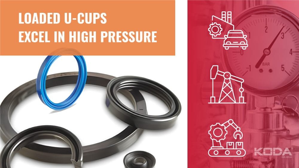
Why Loaded U-Cups Excel in High-Pressure Sealing Applications
High-pressure hydraulic and pneumatic systems place demanding requirements on sealing elements. As pressure rises, a seal must maintain contact with the mating surface, resist extrusion, tolerate repeated movement, manage friction, and survive exposure to temperature and hydraulic media. Among the sealing profiles designed for reciprocating applications, the U-Cups seal is widely r/ecognized for its efficient lip geometry and ability to generate sealing force under operating pressure.
A loaded U-Cup takes this principle further by incorporating an energizing element, such as an elastomeric O-ring or another spring-like component, into the sealing profile. The energizer helps maintain lip contact when system pressure is low, while hydraulic pressure can load the sealing lips during operation. This combination makes loaded U-Cups particularly useful in demanding hydraulic cylinders, actuators, industrial machinery, mobile equipment, and other reciprocating applications.
✔ Engineering Insight: The high-pressure capability of a loaded U-Cup does not come from the seal material alone. Reliable performance depends on the interaction between lip geometry, energizer force, pressure distribution, material hardness, extrusion clearance, surface finish, lubrication, temperature, and installation quality.
What Is a Loaded U-Cup Seal?
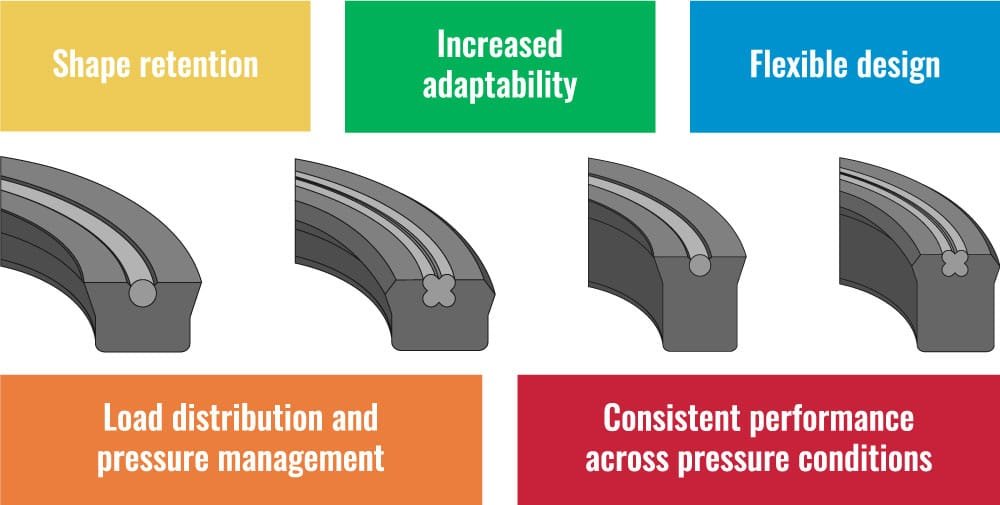
A U-Cup is a polymeric sealing element with a generally U-shaped cross-sectional profile. The two primary sealing lips contact the rod or bore surface, depending on whether the seal is used in a rod-sealing or piston-sealing configuration.
A loaded U-Cup contains an additional energizing element inside or behind the sealing profile. This energizer applies an initial radial force to the sealing lips. When system pressure increases, pressure can enter the internal geometry and further press the sealing lips against the mating surface.
The basic sealing mechanism can be summarized as:
Initial sealing force = Energizer force + Polymer elastic recovery
Operating sealing force = Initial sealing force + Pressure-induced lip loading
This pressure-energized behavior is one of the primary reasons loaded U-Cups can perform effectively in high-pressure reciprocating applications.
Why Loaded U-Cups Excel at High Pressure
At low pressure, a conventional seal must rely primarily on its own elastic recovery and interference fit to maintain contact. As pressure increases, a properly designed loaded U-Cup can use the system pressure to increase lip loading.
This creates a useful relationship between pressure and sealing force. When pressure acts on the appropriate internal surface of the seal, the polymer may be driven more firmly toward the sealing surface.
- ✔ Strong initial sealing at low pressure
- ✔ Increased lip loading under pressure
- ✔ Improved resistance to pressure leakage
- ✔ Reduced risk of seal blow-by when correctly designed
- ✔ Efficient sealing in reciprocating applications
- ✔ Compatibility with a wide range of engineered polymers
However, pressure energization must be carefully controlled. Excessive lip loading can increase friction and heat generation, while insufficient loading may cause leakage at low pressure.
The Role of the Energizer
The energizer is one of the defining characteristics of a loaded U-Cup. In many designs, an elastomeric O-ring is installed within the U-shaped profile. The energizer provides continuous force that supports sealing when hydraulic or pneumatic pressure is low or absent.
For example, during machine start-up, a cylinder may initially have little internal pressure. The energizer helps maintain lip contact before full system pressure is established.
| Condition | Primary Sealing Force |
|---|---|
| System stopped | Energizer and elastic recovery |
| Low pressure | Energizer plus limited pressure loading |
| High pressure | Energizer plus pressure-energized lip loading |
U-Cup Seal Materials for High-Pressure Applications
The polymer selected for a loaded U-Cup strongly influences pressure capability, wear resistance, friction, temperature performance, and chemical compatibility.
Polyurethane
Polyurethane is widely used in hydraulic sealing because it can offer high abrasion resistance, good tear resistance, and relatively high tensile strength. Typical polyurethane sealing compounds may provide tensile strengths ranging approximately from 20 to 50 MPa, depending on formulation and test method.
Polyurethane is frequently selected for mobile hydraulics, construction equipment, cylinders, and applications where abrasive contamination and dynamic movement are important concerns.
PTFE
PTFE provides very low friction and excellent resistance to many chemicals. Because conventional PTFE has limited elastic recovery compared with elastomers, it is often combined with an elastomeric energizer in pressure-energized sealing designs.
Filled PTFE compounds may improve wear resistance, deformation resistance, or load-bearing capability. The exact filler system must be selected according to the application.
NBR
Nitrile rubber is widely used as an energizer material because of its oil resistance and balanced mechanical properties. Typical NBR compounds are available in several hardness grades, commonly around 70 Shore A for general sealing applications.
FKM
FKM is selected when higher temperature capability and resistance to fuels, oils, and many aggressive chemicals are required. The actual operating temperature limit depends on the specific formulation and exposure conditions.
EPDM
EPDM is commonly used with hot water, steam, and many polar fluids. It is generally not suitable for petroleum-based oils unless a specific compatible formulation is confirmed.
Material Comparison for Loaded U-Cups
| Material | Typical Hardness | Typical Temperature Range | Main Strength |
|---|---|---|---|
| Polyurethane | 80–95 Shore A | Approximately -40°C to 100°C | Wear and tear resistance |
| PTFE | Not normally expressed as Shore A | Approximately -200°C to 260°C | Low friction and chemical resistance |
| NBR | 60–90 Shore A | Approximately -40°C to 120°C | Oil resistance |
| FKM | 70–90 Shore A | Approximately -20°C to 200°C | Heat and chemical resistance |
These are general engineering ranges. Actual performance must be confirmed using the specific compound manufacturer’s technical data.
Hardness and High-Pressure Performance
Hardness is commonly measured according to methods such as ASTM D2240 or ISO 48. Harder materials generally provide greater resistance to extrusion and deformation, but excessive hardness may increase friction and reduce the ability of the seal to accommodate surface imperfections.
For high-pressure applications, a common engineering approach is to select a harder sealing material or use a material with superior resistance to deformation and extrusion.
Expert Tip: Pressure capability is not determined by hardness alone. A 90 Shore A seal may still fail if the extrusion gap, temperature, surface finish, or groove geometry is unsuitable.
Extrusion Resistance: A Critical High-Pressure Property
Extrusion occurs when pressure forces a seal into the clearance gap between mating components. At high pressure, this can create a thin protruding lip that is gradually damaged or torn away.
The risk of extrusion increases with:
- Higher system pressure
- Larger extrusion clearance
- Lower material hardness
- Higher operating temperature
- Repeated pressure cycling
- Mechanical misalignment
For certain applications, backup rings may be used to reduce the effective extrusion gap. However, backup-ring design must consider pressure direction, movement, groove geometry, and installation conditions.
A Simple Pressure and Area Calculation
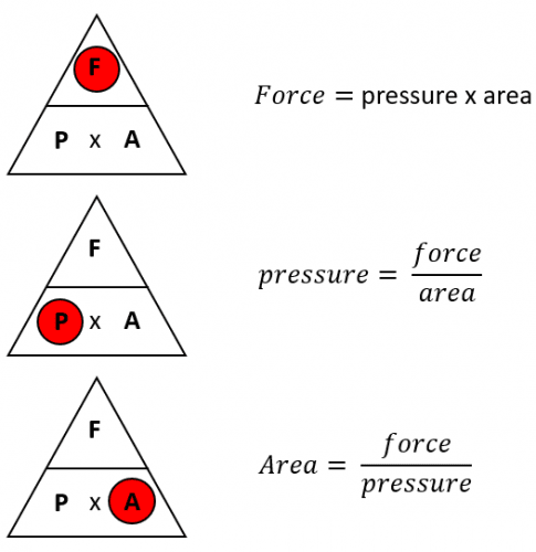
Hydraulic force is commonly estimated using:
Force = Pressure × Area
F = P × A
For example, a hydraulic system operating at 20 MPa over an effective piston area of 0.01 m² theoretically generates:
F = 20,000,000 Pa × 0.01 m² = 200,000 N
This example demonstrates why even a relatively small seal may be exposed to significant mechanical forces in high-pressure hydraulic equipment.
The calculation is simplified and does not account for friction, dynamic effects, pressure losses, rod loads, or system-specific geometry.
Pressure Ratings Must Be Application-Specific
There is no universal maximum pressure rating for every loaded U-Cup. A seal’s pressure capability depends on its profile, material, hardness, extrusion clearance, temperature, speed, pressure cycling, and installation design.
| Design Factor | Effect on High-Pressure Performance |
|---|---|
| Material hardness | Influences extrusion resistance |
| Clearance gap | Controls extrusion risk |
| Temperature | Changes modulus and strength |
| Pressure cycling | Influences fatigue and wear |
| Surface finish | Affects friction and leakage |
Surface Finish and Friction
High-pressure performance is closely connected to the quality of the mating surface. A surface that is too rough may abrade the seal lip. A surface that is too smooth may reduce the ability of the surface to retain a suitable lubricant film in some applications.
The appropriate surface finish depends on the seal material, speed, pressure, lubrication, and application design. Engineers should follow the seal manufacturer’s recommended surface finish range rather than applying one universal value to every U-Cup profile.
Friction is also affected by material hardness, lip geometry, lubrication, pressure, surface finish, and temperature.
Thermal Effects and Heat Generation
In dynamic sealing systems, friction converts mechanical energy into heat. Because elastomers and many polymers have relatively low thermal conductivity, heat can accumulate in the sealing region.
Typical elastomer thermal conductivity values are often approximately 0.13–0.30 W/m·K, while PTFE is also a relatively low thermal conductor compared with metals. Filled compounds may exhibit different values.
Excessive heat may cause:
- Loss of material strength
- Increased wear
- Hardening or softening
- Accelerated chemical aging
- Loss of elastic recovery
Chemical and Corrosion Resistance
The seal itself may not corrode in the same manner as a metal component, but chemical exposure can degrade the polymer or energizer. In addition, the metal housing, rod, bore, or gland may experience corrosion that damages the sealing surface.
Typical compatibility considerations include:
- Hydraulic oils
- Mineral oils
- Water-glycol fluids
- Fire-resistant hydraulic fluids
- Cleaning agents
- Saltwater and moisture
- Fuels and solvents
ASTM D471 immersion testing is commonly used to evaluate changes in rubber properties after exposure to liquids. However, application-specific testing remains important because actual service conditions may include pressure, temperature, dynamic movement, and fluid contamination.
Relevant ASTM and ISO Standards
Depending on the application, engineers may reference several standards when evaluating materials and sealing components.
- ASTM D2240: Durometer hardness testing.
- ASTM D412: Tensile properties of vulcanized rubber and thermoplastic elastomers.
- ASTM D395: Compression set testing.
- ASTM D471: Effect of liquids on rubber properties.
- ASTM D2000: Classification of rubber materials for automotive applications.
- ISO 48: Hardness of vulcanized and thermoplastic rubber.
- ISO 815: Compression set of vulcanized or thermoplastic rubber.
- ISO 1817: Effect of liquids on vulcanized or thermoplastic rubber.
The exact standard used should match the material type, product specification, and application requirements.
Typical Applications for Loaded U-Cups
- Hydraulic cylinders
- Mobile construction equipment
- Mining machinery
- Industrial presses
- Injection molding equipment
- Hydraulic power units
- Pneumatic actuators
- Oil and gas equipment
- Material handling machinery
- Heavy-duty industrial automation
Loaded U-Cups are especially useful when a reciprocating component must maintain reliable sealing under changing pressure conditions.
Installation Method for a Loaded U-Cup
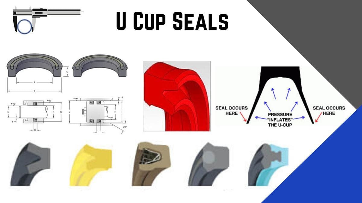
Correct installation is essential because a damaged lip may fail immediately or develop a crack during pressure cycling.
Step 1: Inspect the Groove
Confirm that the groove dimensions match the seal design. Check for burrs, sharp corners, contamination, and surface damage.
Step 2: Inspect the Seal
Check the U-Cup for cuts, nicks, deformation, contamination, or damage caused by improper storage.
Step 3: Use Compatible Lubrication
Where appropriate, apply a lubricant compatible with both the seal material and the operating fluid.
Step 4: Avoid Lip Damage
Do not drag the sealing lip over sharp edges. Use suitable installation tools and protect the seal from threads, ports, and machining features.
Step 5: Confirm Orientation
Install the U-Cup so that the pressure side corresponds to the intended sealing direction. Incorrect orientation can significantly reduce pressure performance.
Loaded U-Cup vs. Conventional U-Cup
| Feature | Loaded U-Cup | Conventional U-Cup |
|---|---|---|
| Low-pressure sealing | Supported by energizer | Depends primarily on elastic recovery |
| Pressure energization | Strong potential | Depends on profile design |
| Dynamic performance | Can be highly effective when optimized | Varies by design |
| Design complexity | Higher | Generally lower |
Failure Mode Analysis
Failure Mode Analysis — Illustrative Industry Example
A loaded U-Cup installed in a hydraulic cylinder begins to show leakage after repeated high-pressure cycles. Inspection reveals a thin, damaged section of polymer at the extrusion gap. The likely mechanism is pressure-driven extrusion caused by a combination of excessive clearance, high pressure, elevated temperature, or insufficient material resistance.
A proper investigation would review operating pressure, pressure spikes, temperature, material hardness, gland dimensions, rod alignment, surface finish, and the condition of any backup components.
This is an illustrative failure analysis based on common industry mechanisms. It is not a report of a specific customer, factory, or proprietary test program.
Case Example: High-Pressure Hydraulic Cylinder
Case Example — Industry Experience Scenario
Consider a hydraulic cylinder operating under repeated pressure cycles. The original seal design experiences occasional leakage after long-term operation. An engineering review identifies a combination of high pressure, dynamic reciprocation, and a relatively large clearance gap.
The design team evaluates a pressure-energized loaded U-Cup made from a higher-performance polymer with improved resistance to extrusion and wear. The review also considers groove geometry, surface finish, temperature, and lubrication.
The important engineering lesson is that changing only the seal material may not solve the problem. The sealing system must be evaluated as a complete assembly.
This scenario is an illustrative industry example and does not represent actual customer test data, guaranteed service life, or a documented factory result.
Laboratory Test Example
Laboratory Test Example — Demonstration Only
A laboratory evaluation of a loaded U-Cup may include static pressure testing, reciprocating wear testing, leakage monitoring, temperature measurement, and post-test visual inspection.
A simplified test program could compare two materials under controlled conditions:
- Defined pressure level
- Defined temperature
- Controlled stroke length
- Controlled reciprocating speed
- Specified fluid
- Defined number of cycles
Engineers may calculate leakage rate using:
Leakage Rate = Collected Fluid Volume ÷ Test Time
Material properties may also be evaluated before and after fluid exposure using methods such as ASTM D471, while hardness can be evaluated using ASTM D2240.
All numerical results must be generated from actual controlled testing. The methodology described here is an example and does not represent real customer data, factory test data, or a predicted service-life curve.
How to Select the Correct Loaded U-Cup
| Selection Question | Why It Matters |
|---|---|
| What is the maximum pressure? | Determines pressure loading and extrusion risk. |
| What is the pressure direction? | Determines seal orientation and profile suitability. |
| What is the temperature range? | Affects polymer strength and elastic recovery. |
| What is the fluid? | Determines chemical compatibility. |
| Is the movement reciprocating? | Influences wear, friction, and lip design. |
| What is the clearance gap? | Controls extrusion risk. |
Common Failure Modes
Extrusion
High pressure may force the seal into a clearance gap, creating nibbling or tearing damage.
Lip Wear
Excessive friction, poor lubrication, rough surfaces, or contamination can wear the sealing lip.
Thermal Degradation
Frictional heating or excessive operating temperature may reduce material strength and elastic recovery.
Chemical Swelling
Incompatible fluids may cause excessive volume change, softening, or loss of mechanical strength.
Energizer Failure
The internal energizer may harden, swell, crack, or lose elasticity, reducing low-pressure sealing performance.
Installation Damage
Cuts, twists, pinching, and sharp-edge damage can create leakage paths that become more severe during pressure cycling.
Expert Tips for High-Pressure U-Cup Design
- ✔ Always evaluate maximum pressure and pressure spikes.
- ✔ Control extrusion clearance carefully.
- ✔ Select hardness according to pressure and movement requirements.
- ✔ Verify compatibility with the actual operating fluid.
- ✔ Consider temperature effects on polymer modulus.
- ✔ Inspect rod and bore surface condition.
- ✔ Avoid assuming that a higher hardness rating solves every problem.
- ✔ Validate critical applications using representative testing.
Final Engineering Perspective
Loaded U-Cups excel in high-pressure sealing because their design combines an initial energizing force with pressure-assisted lip loading. This allows the seal to maintain contact during low-pressure conditions while increasing sealing force as system pressure rises.
However, high-pressure performance is always a system-level engineering problem. The seal profile, polymer, energizer, hardness, pressure, temperature, clearance gap, surface finish, lubrication, alignment, and installation method all contribute to reliability.
The best approach is to begin with the actual operating conditions, select a suitable U-Cups seal material and profile, verify relevant technical data, and validate performance under representative pressure and movement conditions. When these factors are properly balanced, a loaded U-Cup can provide dependable sealing performance in demanding hydraulic and pneumatic systems.
Frequently Asked Questions
1. Why are loaded U-Cups suitable for high-pressure applications?
Loaded U-Cups combine an energizer that provides initial lip force with pressure-energized sealing action. As system pressure increases, the seal geometry can increase contact force against the mating surface.
2. What is the most important material property for a high-pressure U-Cup?
No single property determines performance. Hardness, tensile strength, tear resistance, compression set, wear resistance, chemical compatibility, temperature capability, and extrusion resistance should all be evaluated.
3. Can a loaded U-Cup operate at any pressure?
No. Pressure capability depends on the specific profile, material, hardness, extrusion clearance, temperature, pressure cycling, and installation design. A pressure rating must be application-specific.
4. What causes a high-pressure U-Cup to fail?
Common causes include extrusion, excessive clearance, material incompatibility, thermal degradation, lip wear, poor lubrication, misalignment, pressure spikes, and installation damage.
5. How can engineers improve the service life of a loaded U-Cup?
Use the correct material and profile, control the extrusion gap, maintain suitable surface finish, verify chemical compatibility, control temperature, install the seal correctly, and validate the complete sealing system under representative operating conditions.