Why Choose High-Performance Vulcanized EMI O-Rings?
Modern electronic, aerospace, telecommunications, automotive, medical, defense, and industrial systems increasingly require protection from electromagnetic interference (EMI) and radio-frequency interference (RFI). As electronic systems become smaller, faster, and more densely integrated, unwanted electromagnetic energy can interfere with signal integrity, communication, sensor accuracy, and equipment reliability.
High-performance vulcanized EMI O-Rings provide a specialized solution by combining the elastic sealing function of an O-ring with electrically conductive or shielding properties. These components can help maintain environmental sealing while creating an electrical continuity path across a joint, enclosure, connector, or access panel.
✔ Engineering Insight: An EMI O-ring is not simply a conventional rubber O-ring with conductive filler. Its performance depends on the interaction between elastomer formulation, conductive filler network, vulcanization, compression, joint geometry, surface condition, electrical continuity, and electromagnetic frequency.
What Is a Vulcanized EMI O-Ring?
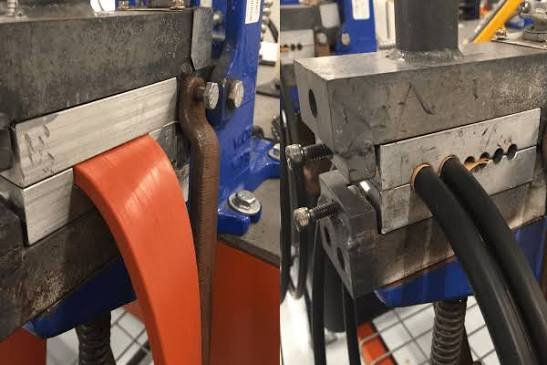
A vulcanized EMI O-ring is an elastomeric sealing component manufactured through a crosslinking process that converts a rubber compound into a stable three-dimensional polymer network. Conductive fillers may be incorporated into the compound to provide electrical conductivity and electromagnetic shielding capability.
Common conductive fillers include:
- ✔ Silver particles
- ✔ Silver-plated copper particles
- ✔ Silver-plated aluminum particles
- ✔ Nickel-coated graphite
- ✔ Carbon-based conductive fillers
- ✔ Other engineered metallic or conductive additives
The final product must maintain two important functions simultaneously:
1. Environmental Sealing: The elastomer must provide compression and resilience against moisture, dust, gases, fluids, or other contaminants.
2. Electromagnetic Shielding: The conductive compound must create a low-resistance electrical path that helps reduce electromagnetic energy passing through the joint.
Why Choose High-Performance Vulcanized EMI O-Rings?
Vulcanized EMI O-rings are often selected when an application requires a combination of electrical shielding and reliable mechanical sealing. Unlike metallic gaskets, elastomeric conductive seals can accommodate certain levels of surface irregularity and provide flexible sealing under compression.
Key advantages include:
- ⚡ Electromagnetic shielding capability
- 💧 Environmental sealing
- 🔧 Flexible installation
- 🔄 Resilience under compression
- 🛡 Protection against dust and moisture
- 🌡 Availability of different temperature-resistant elastomers
- ⚙ Compatibility with complex sealing geometries
For applications where both environmental protection and electrical continuity are required, a properly designed EMI O-Rings solution can simplify the joint design.
How EMI Shielding Works
Electromagnetic shielding works by reducing the transmission of electromagnetic energy through a conductive barrier. When a conductive gasket is compressed between two conductive surfaces, it can create an electrical continuity path across the joint.
For a simplified shielding system:
Shielding Effectiveness (SE) = 10 log₁₀(Pincident / Ptransmitted)
Shielding effectiveness is commonly expressed in decibels (dB). The actual result depends on frequency, material conductivity, gasket geometry, compression, joint design, enclosure structure, and test configuration.
In practical engineering, a high conductivity value alone does not guarantee high shielding effectiveness. A gap, poor compression, discontinuity, or nonconductive surface coating can create an electromagnetic leakage path.
The Importance of Vulcanization
Vulcanization creates crosslinks between polymer chains. This improves the dimensional stability, elasticity, resilience, and mechanical integrity of the elastomer.
For EMI sealing applications, controlled vulcanization is particularly important because the compound must achieve a balance between electrical conductivity and mechanical performance.
| Property | Why It Matters |
|---|---|
| Crosslink density | Influences elasticity and compression recovery |
| Filler dispersion | Influences electrical conductivity consistency |
| Cure uniformity | Influences mechanical and dimensional stability |
| Surface condition | Influences electrical contact and sealing |
Common Elastomer Materials for EMI O-Rings
Silicone
Silicone is commonly selected for wide temperature flexibility and good resistance to aging. It can be formulated with conductive fillers to provide EMI shielding properties.
Typical silicone compounds may operate across a broad temperature range, often approximately from -60°C to 200°C depending on formulation and application conditions.
Fluorosilicone
Fluorosilicone combines silicone-like temperature performance with improved resistance to certain fuels and oils. It is often considered for aerospace and fuel-exposed environments.
EPDM
EPDM may be suitable for water, moisture, and weathering environments, although the specific conductive formulation must be evaluated for electrical and chemical performance.
NBR
NBR offers useful resistance to many petroleum-based oils and fuels. Conductive NBR formulations may be considered where oil resistance and electrical conductivity are both required.
FKM
FKM is often selected for demanding chemical and high-temperature environments. Conductive FKM compounds may provide improved resistance to fuels, oils, and elevated temperatures compared with many general-purpose elastomers.
Material Comparison
| Material | Typical Hardness Range | Typical Temperature Capability | Typical Strength |
|---|---|---|---|
| Silicone | 50–80 Shore A | Approximately -60°C to 200°C | Wide temperature flexibility |
| Fluorosilicone | 60–80 Shore A | Approximately -60°C to 175°C | Fuel and temperature resistance |
| NBR | 60–90 Shore A | Approximately -40°C to 120°C | Oil resistance |
| FKM | 70–90 Shore A | Approximately -20°C to 200°C | Chemical and heat resistance |
These values are general engineering ranges. Conductive fillers, compound formulation, cure system, and manufacturer-specific grades can significantly change the final properties.
Electrical Conductivity and Volume Resistivity
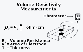
Electrical performance is commonly evaluated using volume resistivity or surface resistivity. Conductive elastomer compounds may be formulated to achieve a wide range of electrical resistance values.
Volume resistivity is commonly expressed in ohm-centimeters (Ω·cm). Lower values generally indicate better bulk electrical conductivity.
Important: The electrical resistance of an EMI O-ring can vary with filler concentration, filler orientation, compression, temperature, aging, contact pressure, and measurement method.
A material with low bulk resistivity may still produce poor shielding performance if the gasket does not maintain continuous electrical contact with the enclosure.
Compression and Electrical Continuity
Compression plays two important roles in an EMI O-ring.
- ✔ It creates environmental sealing force.
- ✔ It improves physical contact between the conductive gasket and mating surfaces.
Insufficient compression may cause both environmental leakage and electrical discontinuity. Excessive compression may increase assembly force, damage the gasket, or cause permanent deformation.
For a simplified compression calculation:
Compression (%) = (Original Cross-Section − Compressed Cross-Section) ÷ Original Cross-Section × 100
For example, if an O-ring has a 5 mm cross-section and is compressed to 4 mm:
Compression = (5 − 4) ÷ 5 × 100 = 20%
The correct compression range depends on the specific EMI O-ring profile, material, groove design, static or dynamic application, and manufacturer’s recommendations.
Shielding Effectiveness and Frequency
EMI shielding performance is frequency-dependent. A gasket that performs well at one frequency may not produce identical results at another frequency.
Common frequency ranges of interest may include:
- Low-frequency magnetic fields
- Radio-frequency communication bands
- Microwave frequencies
- High-speed digital electronics
- Wireless communication systems
At higher frequencies, small gaps and discontinuities can become especially significant because electromagnetic wavelengths become shorter.
Expert Tip: Do not select an EMI O-ring solely by its electrical resistance value. Evaluate the complete shielding system, including enclosure design, joint geometry, compression, contact surfaces, and frequency range.
Common Standards and Test Methods
Depending on the product and application, engineers may reference several standards for evaluating elastomeric and electromagnetic performance.
- ASTM D2240: Durometer hardness testing.
- ASTM D412: Tensile properties of vulcanized rubber and thermoplastic elastomers.
- ASTM D395: Compression set testing.
- ASTM D471: Effect of liquids on rubber properties.
- ASTM D257: DC resistance or conductance of insulating materials, with appropriate application considerations.
- ASTM D4935: Electromagnetic shielding effectiveness of planar materials using a coaxial transmission-line method.
- IEEE 299: Measurement of shielding effectiveness of enclosures and shielding materials in applicable test configurations.
- MIL-DTL-83528: Commonly referenced in specifications for electrically conductive elastomeric shielding materials and gaskets.
The appropriate standard depends on whether the evaluation concerns the raw material, gasket, joint, enclosure, or complete system.
Mechanical Properties of High-Performance EMI O-Rings
Electrical conductivity must not compromise the basic mechanical function of the seal. Engineers commonly evaluate:
| Property | Engineering Importance |
|---|---|
| Hardness | Controls compression force and deformation resistance |
| Tensile strength | Indicates resistance to mechanical rupture |
| Elongation | Indicates flexibility during installation |
| Compression set | Indicates long-term sealing recovery |
| Tear strength | Helps resist installation damage |
Thermal Conductivity and Heat Management
Most elastomeric materials have relatively low thermal conductivity, commonly around 0.13–0.30 W/m·K depending on composition and fillers. Conductive fillers can modify thermal behavior, but the final value must be measured for the specific compound.
In EMI applications, heat may originate from the surrounding electronics, environmental temperature, or compression and friction. Elevated temperature can change elastomer modulus, resistance, compression set, and long-term aging behavior.
Thermal design should therefore consider:
- Operating temperature
- Peak temperature
- Thermal cycling
- Heat transfer through the enclosure
- Conductive filler stability
- Long-term compression at temperature
Corrosion and Chemical Resistance
One important advantage of conductive elastomeric shielding materials is that they can be engineered for different chemical environments. However, conductive fillers may create galvanic compatibility considerations when placed against dissimilar metals in humid or corrosive environments.
Engineers should evaluate:
- Salt spray exposure
- Humidity
- Condensation
- Fuel and oil contact
- Cleaning chemicals
- Galvanic interaction between filler and enclosure metals
The elastomer may remain mechanically intact while electrical contact performance changes because of oxidation or corrosion at the interface. For this reason, material compatibility must be considered at both the polymer and metal-contact levels.
Typical Applications
- Aircraft electronics
- Avionics enclosures
- Automotive electronic control units
- Telecommunications equipment
- Medical electronics
- Radar and communication systems
- Industrial control cabinets
- Electric vehicle systems
- High-speed data equipment
- Military and aerospace electronics
In these applications, an EMI O-ring may help protect sensitive electronics while maintaining the mechanical sealing function of an enclosure or connector interface.
Installation Best Practices
Clean the Contact Surfaces
Remove oil, dust, oxide contamination, and foreign particles that may interrupt electrical continuity or damage the elastomer.
Avoid Excessive Stretch
Excessive stretching can reduce the cross-sectional diameter and alter the intended compression profile.
Control Compression
Insufficient compression may create gaps, while excessive compression can increase assembly force and permanent deformation.
Avoid Sharp Edges
Conductive elastomers can be damaged by sharp corners, burrs, or rough machining features.
Maintain Electrical Continuity
Paint, anodizing, oxide layers, and other nonconductive surface treatments may interrupt the electrical path unless the joint design accounts for them.
EMI O-Ring vs. Conventional O-Ring
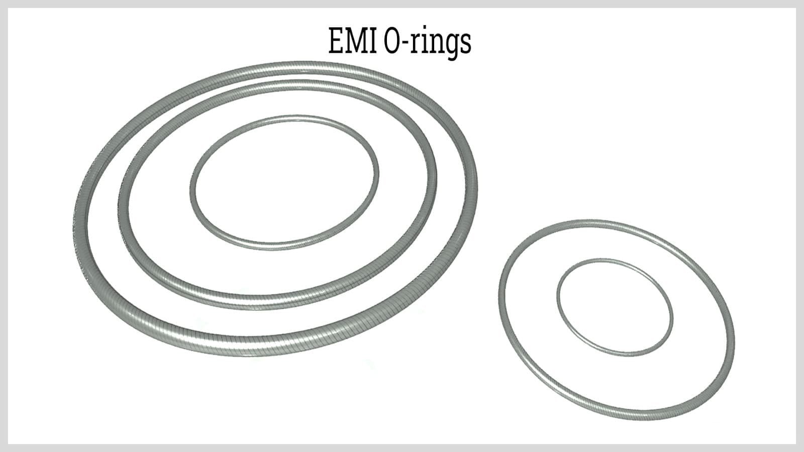
| Feature | EMI O-Ring | Conventional O-Ring |
|---|---|---|
| Environmental sealing | Yes | Yes |
| Electrical conductivity | Designed for conductivity | Usually electrically insulating |
| EMI shielding | Designed for shielding applications | Not normally intended for shielding |
| Material formulation | Conductive fillers | Nonconductive elastomer formulation |
Failure Mode Analysis
Failure Mode Analysis — Illustrative Industry Example
An electronic enclosure experiences increased electromagnetic leakage after repeated maintenance cycles. The EMI O-ring appears visually intact, but electrical continuity across the joint has become inconsistent.
A typical engineering investigation might examine compression loss, contamination, oxidation at the contact surface, surface coatings on the enclosure, mechanical distortion, and gasket damage. The issue may not be caused by the bulk resistivity of the elastomer itself. Instead, the electrical path may have been interrupted at the gasket-to-enclosure interface.
This is an illustrative failure mechanism based on common engineering experience. It is not presented as a documented customer failure or actual factory test result.
Case Example: Shielding an Electronic Enclosure
Case Example — Industry Experience Scenario
Consider a compact electronic enclosure containing high-speed digital circuitry. The enclosure must limit electromagnetic emissions while also protecting the internal electronics from moisture and dust.
An engineering team evaluates a conductive vulcanized EMI O-ring. The design review considers gasket compression, enclosure flatness, contact surface treatment, electrical continuity, operating temperature, and expected maintenance cycles.
The final performance would need to be verified using a defined electromagnetic test method and application-specific environmental testing. The engineering lesson is that gasket material selection alone cannot guarantee enclosure-level shielding effectiveness.
This is an illustrative industry scenario and does not represent a specific customer, factory, or guaranteed test result.
Laboratory Test Example
Laboratory Test Example — Demonstration Only
A laboratory evaluation of a vulcanized EMI O-ring may include separate material and assembly-level tests.
Material-level testing may include:
- Volume resistivity
- Hardness testing
- Tensile strength
- Elongation
- Compression set
- Fluid immersion
- Thermal aging
Assembly-level testing may include:
- Contact resistance
- Shielding effectiveness
- Humidity exposure
- Temperature cycling
- Mechanical compression cycling
For example, an engineer may calculate resistance using:
R = V ÷ I
where R is resistance, V is voltage, and I is current. However, actual EMI performance requires a suitable test configuration because DC resistance alone does not represent shielding effectiveness across all frequencies.
This laboratory test description is an example of an engineering evaluation methodology. It does not contain fabricated customer data, factory test data, or a claimed product performance curve.
How to Choose the Right EMI O-Ring
| Selection Factor | Key Question |
|---|---|
| Frequency | What frequency range must be shielded? |
| Environment | Will the seal face moisture, chemicals, oils, or salt? |
| Temperature | What are the minimum, normal, and maximum temperatures? |
| Compression | Can the joint maintain suitable compression over time? |
| Electrical contact | Are the mating surfaces electrically conductive? |
| Maintenance | Will repeated opening affect gasket compression or contact? |
Common Failure Modes
Loss of Electrical Continuity
Oxidation, contamination, poor compression, surface coatings, or mechanical distortion may interrupt the conductive path.
Compression Set
Long-term compression, especially at elevated temperature, may reduce elastic recovery and weaken both environmental sealing and electrical contact.
Chemical Degradation
Incompatible fluids or cleaning chemicals may swell, harden, soften, or crack the elastomer.
Mechanical Damage
Improper installation can produce cuts, nicks, twists, or permanent deformation.
Galvanic or Contact Corrosion
Conductive fillers and enclosure metals may interact in humid or corrosive environments, potentially affecting long-term contact performance.
Expert Tips for EMI O-Ring Design
- ⚡ Define the target frequency range before selecting the material.
- ✔ Evaluate both shielding and environmental sealing requirements.
- ✔ Verify electrical continuity under actual compression conditions.
- ✔ Consider the effect of surface coatings and oxide layers.
- ✔ Evaluate chemical compatibility with the complete environment.
- ✔ Test the complete enclosure or joint, not only the raw elastomer.
- ✔ Consider thermal aging and compression set for long-term applications.
- ✔ Use application-specific validation for critical electronic systems.
Final Engineering Perspective
High-performance vulcanized EMI O-rings are valuable because they combine two functions that are often required in modern electronic equipment: environmental sealing and electromagnetic shielding.
The vulcanized elastomer provides resilience and compression recovery, while conductive fillers create an electrical path across the joint. However, the final shielding performance depends on the complete system. Material conductivity, gasket compression, surface condition, enclosure geometry, frequency, temperature, moisture, and mechanical aging all influence the result.
For engineers selecting EMI O-Rings, the most reliable process is to define the electromagnetic requirements first, identify the environmental and mechanical conditions, select a compatible elastomer and conductive filler system, and then validate the complete joint using appropriate electrical and electromagnetic testing.
When properly designed and tested, a high-performance vulcanized EMI O-ring can provide a practical, flexible, and durable solution for demanding shielding and sealing applications.
Frequently Asked Questions
1. What is an EMI O-ring?
An EMI O-ring is a conductive elastomeric sealing component designed to provide environmental sealing while helping create an electrical continuity path for electromagnetic shielding.
2. Why are vulcanized EMI O-rings used?
Vulcanization improves the elastomer’s dimensional stability, elasticity, resilience, and mechanical integrity. These properties help the gasket maintain compression and sealing performance over time.
3. What materials are commonly used for EMI O-rings?
Common elastomer bases include silicone, fluorosilicone, NBR, EPDM, and FKM. Conductive fillers such as silver, silver-plated metals, nickel-coated graphite, and carbon-based materials may be used depending on electrical and environmental requirements.
4. Does low electrical resistance automatically mean excellent EMI shielding?
No. Shielding performance also depends on frequency, compression, joint geometry, surface condition, electrical continuity, enclosure design, and the presence of gaps or discontinuities.
5. How should engineers select an EMI O-ring?
Consider the required frequency range, shielding target, temperature, chemical exposure, compression, enclosure materials, surface treatments, mechanical requirements, maintenance conditions, and applicable test standards before selecting the final material and design.