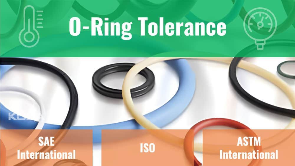
O-ring tolerance is one of the most important but frequently underestimated factors in sealing-system design. An O-ring may have the correct nominal size, material, hardness, and compound designation, yet still fail to seal reliably if its dimensional tolerance is not appropriate for the application. For engineers, purchasers, maintenance teams, and manufacturers, understanding O-ring tolerance means understanding how small dimensional variations influence squeeze, stretch, gland fill, extrusion resistance, friction, leakage, installation force, and long-term reliability.
An O-ring is a precision elastomeric component, but it is not manufactured to zero dimensional variation. Its inside diameter (ID), outside diameter (OD), and cross-sectional diameter (CS) inevitably vary within specified limits because of mold tolerances, elastomer shrinkage, curing conditions, temperature, measurement methods, tooling condition, and material behavior. The purpose of an O-ring tolerance standard is therefore not simply to define how large or small an O-ring may be. It establishes a controlled dimensional window within which the seal is expected to perform correctly.
For engineers selecting or designing O-rings, the key question is not simply “What is the nominal O-ring size?” but rather “What dimensional variation can the sealing system safely tolerate?” This distinction becomes especially important in hydraulic cylinders, pneumatic equipment, automotive systems, refrigeration and air-conditioning equipment, pumps, valves, industrial machinery, fuel systems, and precision fluid-control assemblies.
🔎 Engineering takeaway: O-ring tolerance must always be evaluated together with groove dimensions, compression, pressure, temperature, material hardness, clearance, lubrication, installation method, and media compatibility. A dimensionally acceptable O-ring can still fail if the gland design is wrong.
What Is O-Ring Tolerance?

O-ring tolerance is the permitted dimensional variation around the nominal dimensions of an O-ring. The three primary dimensional characteristics are inside diameter (ID), outside diameter (OD), and cross-sectional diameter (CS). Depending on the specification and manufacturing method, additional requirements may apply to flash, parting lines, surface imperfections, concentricity, and dimensional stability.
For example, an O-ring may have a nominal cross-section of 2.00 mm. It cannot realistically be manufactured so that every part measures exactly 2.000 mm. Instead, the applicable specification defines an allowable range. If the permitted range were hypothetically 1.95–2.05 mm, an individual part measuring 1.97 mm or 2.03 mm could still conform to that dimensional requirement.
This dimensional variation matters because the sealing force generated by an O-ring depends heavily on its cross-sectional compression. If the cross-section is smaller than expected, compression may decrease. If it is larger than expected, compression may increase and cause excessive friction, assembly force, deformation, or accelerated wear.
For this reason, O-ring tolerance should be viewed as part of a tolerance stack-up rather than as an isolated manufacturing number.
Why O-Ring Tolerance Matters to Sealing Performance
An O-ring normally seals by being elastically compressed between mating surfaces. The compressed elastomer creates contact pressure against the sealing surfaces. This contact pressure must be high enough to prevent the working fluid or gas from passing through microscopic leakage paths.
However, more compression does not automatically mean better sealing. Excessive compression can increase friction, installation force, heat generation, wear, extrusion risk, and permanent deformation. The engineering objective is therefore to maintain an appropriate compression range across the complete manufacturing tolerance stack.
Consider a simplified static sealing arrangement with a nominal O-ring cross-section of 3.00 mm. If the groove depth produces 20% nominal compression, the nominal compressed height is approximately:
Compression calculation:
Compression = (Original CS − Compressed Height) ÷ Original CS × 100%
At 20% compression:
Compressed Height = 3.00 × (1 − 0.20) = 2.40 mm
If the actual O-ring cross-section is larger or smaller because of manufacturing tolerance, the actual compression changes even though the metal groove has not changed.
This simple example demonstrates why tolerance is directly connected to seal performance. A designer who considers only nominal dimensions may overlook the actual minimum and maximum compression conditions.
The Three Critical O-Ring Dimensions
Inside Diameter (ID)
The inside diameter is particularly important for dynamic seals and applications where the O-ring is stretched over a shaft, piston, plug, or other cylindrical component. Excessive ID variation can change the amount of stretch during installation.
O-ring stretch influences the effective cross-section and contact pressure. When an O-ring is stretched, its cross-section generally becomes slightly smaller because elastomer volume is approximately conserved. Therefore, excessive stretch can reduce the radial or axial sealing geometry available to the designer.
For a simple engineering estimate, O-ring ID stretch can be calculated as:
Stretch (%) = (Installed ID − Free ID) ÷ Free ID × 100%
For example, if an O-ring has a free ID of 50.00 mm and is installed over a 51.00 mm shaft:
Stretch = (51.00 − 50.00) ÷ 50.00 × 100% = 2%
A 2% nominal stretch may be acceptable in many applications, but the correct range depends on the seal geometry, material, application type, and applicable engineering standard. Tolerance must be included because the actual ID may not be exactly 50.00 mm.
Outside Diameter (OD)
The OD becomes especially important in static radial sealing applications where the O-ring sits inside a bore or housing groove. Excessive OD variation can influence installation, groove fill, radial compression, and the risk of pinching during assembly.
In applications where the O-ring must be inserted into a blind groove or bore, a larger-than-expected OD may increase installation resistance. A smaller OD may reduce contact pressure or create an assembly condition in which the O-ring does not remain properly positioned.
Cross-Section (CS)
Cross-sectional diameter is often the most critical dimension because it directly affects squeeze. Small variations in CS can produce relatively large changes in compression percentage, particularly with small O-rings.
For example, if an O-ring nominally has a 1.50 mm cross-section and the groove produces a 0.30 mm reduction in height, nominal compression is:
0.30 ÷ 1.50 × 100% = 20%
If manufacturing variation causes the actual cross-section to be 1.45 mm, the same groove geometry can create a different compression ratio. Conversely, if the cross-section is 1.55 mm, compression increases.
This is why precision applications should not select a tolerance class based only on purchase price. The tolerance should be selected according to the sensitivity of the sealing system.
Common O-Ring Standards: ISO 3601 and AS568
Two references frequently encountered in industrial O-ring engineering are ISO 3601 and AS568. They serve related but different roles within O-ring dimensional control and identification.
AS568, historically associated with SAE International, is widely used in North America to define standard O-ring dash sizes and nominal dimensions. It is common in hydraulic, pneumatic, automotive, aerospace, industrial, and general mechanical applications.
ISO 3601 provides an internationally recognized framework for O-rings, including dimensional requirements and quality characteristics for specified applications. ISO 3601 is especially relevant where international procurement, metric engineering, and standardized sealing components are involved.
Engineers should always verify the current revision and the specific part classification applicable to their application rather than assuming that every O-ring sold under an AS568 or ISO designation has identical dimensional or quality requirements.
For metric applications, a useful engineering reference is O-Ring Tolerance, particularly when comparing metric O-ring dimensional ranges and tolerance considerations.
⚙️ Expert tip: Never assume that a nominal metric O-ring and an inch-series O-ring are interchangeable simply because their dimensions appear close. The resulting change in cross-section, stretch, and groove occupancy can be enough to change sealing performance.
O-Ring Tolerance Classes and Manufacturing Quality
O-ring specifications may distinguish between different dimensional quality levels or application classes. The exact classification terminology depends on the standard being used. Higher precision generally means tighter permissible dimensional variation, but it may also increase manufacturing cost.
The important engineering principle is that the tightest possible tolerance is not always the best economic choice. If an application uses a large, low-pressure static seal with generous gland dimensions and relatively low sensitivity to dimensional variation, an unnecessarily tight tolerance may provide little practical benefit.
On the other hand, miniature seals, high-pressure hydraulic components, precision valves, low-friction dynamic systems, and automated assembly equipment can be much more sensitive to dimensional variation.
| Application | Tolerance Sensitivity | Primary Concern |
|---|---|---|
| Low-pressure static housing seal | Low–Medium | Reliable compression and assembly |
| Hydraulic cylinder | Medium–High | Extrusion, friction and leakage |
| High-speed pneumatic actuator | High | Friction, wear and dynamic stability |
| Miniature valve | Very High | Dimensional stack-up and leakage |
| Automotive AC connection | High | Leakage, assembly and refrigerant compatibility |
How Tolerance Affects O-Ring Squeeze
Squeeze is one of the most important design parameters for an O-ring. In a static application, the designer typically specifies a target compression range appropriate to the geometry and material.
For axial sealing, the basic compression relationship can be expressed as:
Axial squeeze (%) = (O-ring CS − Gland height) ÷ O-ring CS × 100%
For radial sealing, the exact geometry becomes more complicated because the O-ring may interact with the shaft, bore, groove width, and clearance. Nevertheless, the fundamental concept remains the same: dimensional variation changes the amount of elastomer deformation.
A tolerance stack-up should include at least:
• Minimum and maximum O-ring cross-section
• Minimum and maximum groove depth
• Surface dimensional tolerances
• Shaft or bore tolerance
• Thermal expansion
• Material swelling or shrinkage
• Installation stretch
• Pressure-induced deformation
Ignoring any one of these factors can lead to a design that works at nominal dimensions but fails at the worst-case combination of tolerances.
Tolerance Stack-Up: A Practical Example
Case Example — Static Hydraulic Housing Seal
The following is an engineering example intended to demonstrate the method. It is not presented as a report from a specific customer or factory, and it does not represent a guaranteed life prediction.
Assume an O-ring has a nominal cross-section of 3.00 mm. The groove is designed to provide a nominal compressed height of 2.40 mm.
Nominal compression is therefore:
(3.00 − 2.40) ÷ 3.00 × 100% = 20%
Now assume the actual O-ring cross-section can vary around the nominal value. If the actual cross-section is lower, the compression percentage decreases. If the cross-section is higher, the compression percentage increases.
At the same time, the groove depth can also vary because the groove is machined within its own dimensional tolerance. The worst-case low-compression condition may occur when the O-ring is at its smallest permissible cross-section and the groove is at its deepest permissible dimension.
The worst-case high-compression condition occurs when the O-ring is at its largest permissible cross-section and the groove is at its shallowest permissible dimension.
📐 Engineering principle: Always evaluate both ends of the tolerance range. Designing only around nominal dimensions can hide the exact conditions most likely to create leakage or excessive friction.
O-Ring Hardness and Its Relationship With Tolerance
O-ring hardness is commonly expressed in Shore A. Typical industrial elastomer hardness values may include approximately 70 Shore A, although 60, 75, 80, 90 and other hardness levels are also used depending on the compound and application.
Hardness should not be confused with dimensional tolerance. Two O-rings can have identical dimensions and very different hardness, while two O-rings of the same hardness can have different dimensional tolerances.
Hardness affects how the O-ring responds to compression, pressure, extrusion, installation, and dynamic movement. Softer compounds can conform effectively to surface irregularities but may be more vulnerable to extrusion under high pressure or large clearance. Harder compounds can offer greater extrusion resistance but may require higher assembly force and may be less forgiving of surface imperfections.
In practical design, tolerance and hardness must therefore be considered together.
| Hardness Range | Typical Characteristics | Engineering Consideration |
|---|---|---|
| Around 60 Shore A | Soft, good conformity | Consider extrusion and handling |
| Around 70 Shore A | Common general-purpose balance | Suitable for many industrial sealing designs |
| Around 80 Shore A | Higher resistance to deformation | May increase assembly and friction requirements |
| Around 90 Shore A | High hardness | Useful where extrusion resistance is important |
These ranges are illustrative engineering categories rather than universal material specifications. Actual mechanical properties vary by polymer family, formulation, cure system, temperature, test method, and manufacturer.
Material Selection and O-Ring Tolerance
Dimensional tolerance alone cannot guarantee sealing performance. The elastomer must also be compatible with the operating environment.
NBR (Nitrile): NBR is widely used for mineral oils, hydraulic fluids, fuels, and general industrial applications. Its temperature capability and chemical resistance depend strongly on formulation. NBR is often available in different acrylonitrile content grades, which influence oil resistance, flexibility, and low-temperature performance.
FKM (Fluorocarbon): FKM is widely selected where elevated temperature and resistance to many oils, fuels, and chemicals are required. Its actual performance depends on the specific formulation and fluid.
EPDM: EPDM is commonly used with water, steam in suitable grades, glycol-based fluids, and many polar chemicals. Standard EPDM should generally not be selected for petroleum-based oils unless a specially compatible formulation is verified.
Silicone: Silicone elastomers offer broad temperature capability and flexibility but are not universally suitable for every mechanical or fluid environment.
FFKM: FFKM can provide exceptional chemical and high-temperature resistance, but cost is significantly higher than many general-purpose elastomers.
Material selection should therefore be based on temperature, pressure, fluid, mechanical movement, compression set, friction, regulatory requirements, and expected service conditions—not simply O-ring color or nominal hardness.
Temperature Can Change Effective O-Ring Tolerance
Elastomers are temperature-sensitive materials. Temperature changes can influence dimensions, modulus, hardness, compression set, and chemical swelling.
Thermal expansion of the surrounding metal components also changes the gland geometry. Steel, aluminum, stainless steel, and other materials have different coefficients of thermal expansion. Consequently, an O-ring system that performs correctly at room temperature may experience different compression at operating temperature.
This is particularly important in automotive, refrigeration, engine, compressor, hydraulic, and high-temperature industrial applications.
Thermal design should therefore evaluate:
• Minimum operating temperature
• Maximum operating temperature
• Temperature cycling
• Elastomer glass-transition behavior
• Compression set at temperature
• Thermal expansion of the housing
• Thermal expansion of the mating component
• Fluid viscosity changes
🔥 Expert tip: A room-temperature dimensional inspection cannot by itself prove that an O-ring will maintain adequate sealing compression throughout the full operating temperature range.
Thermal Conductivity and O-Ring Engineering
Elastomers generally have much lower thermal conductivity than metals. For many rubber compounds, thermal conductivity is commonly on the order of roughly 0.1–0.3 W/(m·K), although actual values vary substantially by polymer, filler system, temperature, and formulation.
By comparison, metals such as aluminum and copper have thermal conductivities that are orders of magnitude higher. This difference means an O-ring can experience a thermal environment that is not identical to the surrounding metal structure, especially during rapid temperature changes.
Thermal conductivity is usually not the primary selection parameter for an O-ring, but it becomes relevant in high-temperature seals, thermal cycling, cryogenic systems, and applications with steep temperature gradients.
O-Ring Tolerance and Pressure Resistance
Pressure does not simply push an O-ring harder against a sealing surface. At sufficient pressure, the elastomer can be forced into the clearance gap between mating components. This phenomenon is commonly called extrusion.
The risk of extrusion depends on pressure, temperature, material hardness, clearance, O-ring cross-section, groove geometry, and the presence or absence of backup rings.
A smaller-than-expected O-ring may not occupy the gland as intended, while an oversized O-ring may create excessive assembly interference. Therefore, dimensional tolerance must be considered together with extrusion gap requirements.
For high-pressure hydraulic systems, the engineer should use the applicable gland design recommendations and verify the maximum permissible clearance for the selected material hardness and pressure condition rather than relying on a generic O-ring tolerance value.
O-Ring Tolerance and Clearance
Clearance is the space into which the O-ring may extrude under pressure. A small dimensional change in the O-ring or gland can therefore have a significant impact on the actual sealing geometry.
High pressure, elevated temperature, soft elastomer, large clearance, and dynamic movement can combine to increase extrusion risk.
When the application operates at high pressure, engineers may use a harder compound or a backup ring. However, backup-ring selection also requires attention to geometry, installation, pressure direction, material compatibility, and dynamic behavior.
O-Ring Surface Finish and Dimensional Accuracy
An O-ring does not seal against dimensions alone. Surface finish is equally important. A metal sealing surface that is too rough can damage the elastomer or create leakage channels. A surface that is excessively smooth may also influence lubrication and dynamic friction.
Surface finish requirements should be selected according to the application and applicable sealing standard rather than using one universal roughness value for every O-ring.
Typical engineering considerations include:
• No sharp machining edges
• No burrs
• No deep scratches crossing the sealing path
• Appropriate surface roughness
• Correct lead-in chamfers
• Controlled groove geometry
• Clean installation surfaces
Dimensional tolerance and surface finish must therefore be treated as complementary quality requirements.
Installation: Why a Correctly Toleranced O-Ring Can Still Fail
Installation damage is one of the most common practical causes of O-ring leakage. A part can meet dimensional specifications and still fail immediately if it is cut, twisted, stretched excessively, contaminated, or pinched during assembly.
Before installation, inspect the groove and mating components. Remove burrs, metal particles, machining debris, and sharp edges. Use a compatible lubricant where permitted by the application.
During installation, avoid twisting the O-ring. A twisted O-ring can develop localized stress and may roll or extrude during operation.
For dynamic applications, the installation path should be designed with appropriate chamfers and radii. Tools with sharp edges should not be allowed to contact the sealing surface.
🛠️ Installation checklist: Clean groove → inspect edges → verify dimensions → apply compatible lubricant if permitted → install without twisting → confirm seating → assemble carefully → inspect for pinching or displacement.
Common O-Ring Failure Modes Related to Tolerance
1. Leakage Caused by Insufficient Compression
If the O-ring cross-section is too small, the gland is too deep, or the tolerance stack creates insufficient squeeze, contact pressure may be inadequate. Leakage can become particularly apparent during pressure cycling or low-temperature operation.
2. Excessive Friction
Too much compression can increase friction. In dynamic seals, excessive friction can lead to stick-slip behavior, heat generation, wear, and higher actuator force.
3. Pinching
An O-ring that is oversized relative to the gland or installed without sufficient clearance may become pinched during assembly. The resulting cut or permanent deformation can produce an immediate leak.
4. Extrusion
High pressure combined with excessive clearance and insufficient material hardness can push the O-ring into the gap. Repeated pressure cycling can accelerate nibbling and eventual failure.
5. Permanent Compression Set
Long-term exposure to heat, pressure, chemicals, and compression can cause an elastomer to lose its ability to recover. Compression set is strongly dependent on compound formulation and service conditions.
6. Installation Damage
A cut, twist, or abrasion introduced during installation can dominate the failure mechanism even when dimensional tolerance is completely compliant.
Failure Mode Analysis Example
Case Example — Hydraulic Valve Leakage
The following scenario is an illustrative industry engineering example and is not presented as a real customer failure report.
A hydraulic valve uses a standard elastomeric O-ring. The nominal size is correct, the compound is compatible with the hydraulic fluid, and the hardness is approximately 70 Shore A. Leakage is observed after repeated pressure cycling.
The first assumption might be that the O-ring material is defective. However, an engineering failure investigation should examine the entire sealing system.
Step 1: Dimensional inspection. Measure multiple O-rings rather than one sample. Confirm ID, OD, and cross-section against the applicable specification.
Step 2: Groove inspection. Measure groove depth, width, diameter, and surface condition.
Step 3: Clearance inspection. Determine whether pressure can force the elastomer into an excessive gap.
Step 4: Failure morphology. Look for extrusion nibbling, cuts, abrasion, flattening, swelling, cracking, or chemical attack.
Step 5: Installation review. Inspect whether the seal was twisted or damaged during assembly.
Step 6: Pressure and temperature review. Compare actual operating conditions against the design assumptions.
This systematic process often identifies the true root cause more effectively than simply changing the O-ring compound.
Laboratory Test Example: Evaluating O-Ring Dimensional Consistency
The following is a laboratory test example intended to demonstrate a quality-control approach. It does not represent real factory data or a fabricated customer test result.
A manufacturer can sample O-rings from multiple production lots and measure ID, OD, and cross-section using calibrated dimensional equipment appropriate for elastomeric components.
A useful test plan may include:
• Multiple pieces from each production lot
• Measurements at defined locations
• Controlled measurement temperature
• Calibrated measuring instruments
• Traceable inspection records
• Comparison with the applicable standard
• Statistical analysis of the measured population
The resulting data can be used to determine average dimension, range, standard deviation, and process capability. Statistical process control can help manufacturers identify tool wear, curing variation, or process drift before nonconforming parts reach customers.
For elastomers, measurement technique is important. Excessive measuring force can deform a soft O-ring and produce misleading results. Therefore, the inspection method should be appropriate to the material and standard.
O-Ring Tolerance and Compression Set Testing
Dimensional inspection answers the question of whether the manufactured part meets its dimensional specification. Compression-set testing answers a different question: how well the elastomer recovers after being compressed under defined conditions.
ASTM D395 is a commonly referenced standard for compression set of rubber-like materials. ASTM D1414 is widely associated with testing rubber O-rings and includes methods relevant to O-ring physical properties and performance evaluation.
These standards should be used according to their current editions and applicable test methods. Test results should not be interpreted as universal service-life predictions because laboratory conditions may differ substantially from real operating environments.
ASTM and ISO Standards Engineers Commonly Encounter
Depending on the application, O-ring engineering may involve several ASTM, ISO, SAE, and industry specifications.
| Standard | General Relevance |
|---|---|
| ISO 3601 | O-ring dimensions and quality requirements |
| AS568 | Standard inch-series O-ring sizes |
| ASTM D1414 | Testing of rubber O-rings |
| ASTM D395 | Compression set of rubber-like materials |
| ASTM D2240 | Durometer hardness measurement |
The standards listed above do not replace application-specific engineering specifications. Aerospace, automotive, medical, semiconductor, food-processing, and other regulated industries may impose additional requirements.
How to Select the Correct O-Ring Tolerance

A practical selection process begins with the sealing environment rather than the catalog size.
1. Define the application. Determine whether the seal is static axial, static radial, reciprocating, rotary, pneumatic, hydraulic, vacuum, or another configuration.
2. Define the media. Identify oil, water, fuel, refrigerant, hydraulic fluid, air, gas, solvent, steam, or other chemical exposure.
3. Define temperature. Include minimum, maximum, cycling, and transient temperatures.
4. Define pressure. Consider normal pressure, maximum pressure, pressure spikes, and cycling frequency.
5. Select material. Verify chemical compatibility and temperature capability.
6. Select hardness. Consider extrusion, friction, assembly force, and deformation resistance.
7. Determine gland dimensions. Establish groove width, depth, shaft/bore diameter, and clearance.
8. Evaluate tolerance stack-up. Calculate worst-case compression and clearance conditions.
9. Select the applicable O-ring standard. Confirm dimensional and quality requirements.
10. Validate the design. Use representative testing when the application is critical or operating conditions are severe.
Metric O-ring projects should also verify the appropriate dimensional class and tolerances rather than treating all metric seals as interchangeable. A useful reference for this purpose is O-Ring Tolerance.
Tolerance Versus Cost: Is Tighter Always Better?
From a purchasing perspective, it can be tempting to request the smallest possible dimensional tolerance. However, tighter tolerance may require more precise tooling, process control, inspection, sorting, and potentially higher manufacturing costs.
The correct question is whether the sealing application benefits from that additional precision.
For example, a large static O-ring sealing a low-pressure enclosure may have substantial design margin. A very tight tolerance may provide little additional reliability. In contrast, a miniature dynamic valve with a narrow operating window may be highly sensitive to cross-section variation.
The best engineering solution is therefore application-specific tolerance optimization.
O-Ring Tolerance in Automotive Applications
Automotive sealing systems often experience temperature cycling, vibration, pressure changes, chemical exposure, and demanding assembly conditions.
Air-conditioning systems are a good example. O-rings used around refrigerant circuits must tolerate refrigerant exposure, compatible lubricating oil, temperature changes, pressure variation, and repeated assembly in service conditions. The correct material is essential, but dimensional accuracy also matters because connectors and grooves are designed around a specific seal geometry.
Fuel systems introduce additional requirements for chemical compatibility and swelling resistance. Engine and transmission applications can experience elevated temperatures and fluid contamination. Therefore, the correct O-ring compound and dimensional specification must be selected together.
O-Ring Tolerance in Hydraulic Systems
Hydraulic systems can operate at pressures far above those found in many general industrial applications. Consequently, extrusion resistance, hardness, gland clearance, and backup-ring design become particularly important.
A hydraulic seal should not be selected simply by matching the nominal O-ring size. The designer must verify pressure, temperature, dynamic movement, clearance, surface finish, and material compatibility.
Where pressure is high, an apparently small dimensional change can alter the available extrusion gap and compression condition. This is why high-pressure systems require careful gland design and tolerance analysis.
O-Ring Tolerance in Pneumatic Systems
Pneumatic systems may operate at lower pressure than hydraulic systems, but dynamic speed can be significantly higher. Friction, stick-slip, wear, lubrication, and surface finish become important.
An O-ring with excessive compression may create unnecessary friction and increase actuator energy requirements. Conversely, insufficient compression may cause leakage.
For pneumatic cylinders, tolerance should therefore be evaluated together with dynamic sealing geometry and the actual speed profile.
O-Ring Tolerance and Vacuum Applications
Vacuum sealing introduces different considerations because gas leakage can occur through very small paths. Material permeability, surface condition, compression, cleanliness, and outgassing may become more important than in conventional liquid sealing.
A vacuum system may require specialized elastomers, surface treatments, cleaning processes, or design practices. The dimensional tolerance must be compatible with the vacuum level and leakage requirement.
How Manufacturers Control O-Ring Dimensional Tolerance
O-ring manufacturing commonly involves elastomer mixing, molding, curing, deflashing, inspection, and packaging. Dimensional stability can be influenced by compound formulation, mold condition, curing temperature, curing time, shrinkage, storage conditions, and environmental factors.
Manufacturers can improve consistency through controlled molding parameters, properly maintained tooling, process monitoring, calibrated inspection equipment, and statistical quality control.
For critical applications, incoming inspection should verify not only dimensions but also certificate information, material identification, hardness, visual quality, and lot traceability as required by the applicable purchasing specification.
🏭 Manufacturing insight: Dimensional tolerance is a process capability issue as much as a drawing requirement. A supplier that can repeatedly center production around the nominal dimension may provide more stable performance than one that merely sorts occasional parts into the allowable range.
Measurement Methods and Quality Inspection
Measuring elastomeric components requires care because rubber can deform under contact pressure. ID can be evaluated using appropriate gauges or optical measurement systems, while cross-section may be checked with specialized dimensional equipment.
For high-volume production, automated optical inspection can provide fast and repeatable dimensional screening. For engineering validation, calibrated instruments and controlled measurement procedures are essential.
When measuring an O-ring, inspectors should control:
• Temperature
• Measurement force
• Instrument calibration
• Measurement location
• Sample size
• Part conditioning
• Operator technique
Measurements taken under uncontrolled conditions may create false rejection or false acceptance.
Storage Can Also Affect O-Ring Dimensions and Performance
Elastomers can age during storage. Heat, ozone, ultraviolet exposure, humidity, compression, and inappropriate environmental conditions can influence physical properties.
O-rings should generally be stored according to the applicable material and industry storage recommendations. They should be protected from direct sunlight, ozone-generating equipment, excessive heat, and contamination.
Storage damage may manifest as cracking, hardening, surface deterioration, or changes in elasticity. A dimensionally correct but aged O-ring may still perform poorly.
Five Practical Rules for O-Ring Tolerance Engineering
Rule 1 — Never design around nominal dimensions alone. Always examine minimum and maximum conditions.
Rule 2 — Treat the O-ring and gland as one system. O-ring tolerance has little meaning without groove dimensions and clearance.
Rule 3 — Match tolerance to application sensitivity. Precision dynamic and miniature seals generally require more careful dimensional control than low-pressure static seals.
Rule 4 — Verify material compatibility. Dimensional accuracy cannot compensate for chemical attack, excessive swelling, thermal degradation, or compression set.
Rule 5 — Validate critical applications. Laboratory testing and representative application testing are more reliable than assuming catalog data predicts every field condition.
Expert Guide: Questions to Ask an O-Ring Supplier
When purchasing O-rings for an industrial application, ask the supplier to identify the applicable dimensional standard and quality class. Confirm the material designation, hardness range, manufacturing specification, and lot traceability where required.
For critical applications, useful questions include:
• Which dimensional standard applies?
• What tolerance class is supplied?
• What is the specified hardness range?
• What compound family is being supplied?
• Is the material formulation controlled by a defined specification?
• Are dimensions measured under controlled conditions?
• Is lot traceability available?
• What inspection records are available?
• Are certificates of conformity available?
• Has the compound been validated against the actual operating media?
A professional supplier should be able to distinguish between a nominal catalog dimension and the actual controlled manufacturing specification.
Why O-Ring Tolerance Should Be Part of Design Reviews
In many engineering projects, the O-ring is one of the lowest-cost components but can become one of the highest-impact components if it fails. A leaking seal can cause equipment downtime, contamination, fluid loss, pressure loss, warranty claims, safety concerns, or expensive field service.
Including O-ring tolerance in a design review is inexpensive compared with troubleshooting a recurring leakage problem after production release.
A good design review should ask whether the complete tolerance stack maintains sufficient compression, avoids excessive gland fill, maintains acceptable extrusion clearance, and remains functional across the expected temperature and pressure range.
A Practical O-Ring Tolerance Design Checklist
| Design Item | Check |
|---|---|
| O-ring ID | Nominal and tolerance verified |
| O-ring CS | Compression stack-up calculated |
| Groove depth | Minimum/maximum condition checked |
| Groove width | Gland fill checked |
| Clearance | Extrusion risk evaluated |
| Hardness | Specified for pressure and movement |
| Material | Fluid and temperature compatibility verified |
| Surface finish | Sealing surfaces inspected |
| Installation | Twist, pinch and damage risks controlled |
| Testing | Representative validation planned where necessary |
Conclusion: The Importance of O-Ring Tolerance
O-ring tolerance is much more than a dimensional specification on a purchasing drawing. It is a fundamental part of sealing-system reliability. The ID, OD, and cross-sectional tolerances influence stretch, compression, friction, gland fill, installation, extrusion behavior, and leakage performance.
Reliable O-ring design requires the engineer to look beyond the nominal catalog size. ISO 3601, AS568, ASTM test methods, material specifications, hardness requirements, groove geometry, surface finish, pressure, temperature, fluid compatibility, and installation conditions all contribute to the final result.
The most effective approach is to evaluate the complete tolerance stack-up and determine whether the actual sealing system remains within an acceptable operating window under minimum and maximum conditions.
For metric sealing applications, engineers can also review O-Ring Tolerance information when comparing standard metric dimensions and tolerance considerations.
It is also important to distinguish engineering examples from verified product performance. The calculations, case examples, laboratory test approaches, and failure-analysis scenarios presented here are illustrative engineering examples or common industry practices. They are not claims of testing performed for a specific customer, factory, product, or application, and they should not be interpreted as guaranteed service-life curves or field-performance data.
5 Frequently Asked Questions About O-Ring Tolerance
1: Why is O-ring tolerance important?
O-ring tolerance controls the allowable variation in ID, OD, and cross-section. These dimensions directly influence compression, stretch, gland fill, friction, installation, and extrusion resistance. If tolerance is ignored, a sealing system may work at nominal dimensions but fail under worst-case manufacturing conditions.
2: What standards are commonly used for O-ring dimensions?
ISO 3601 and AS568 are two important references used internationally and in North American applications. ISO 3601 is widely used for O-ring dimensional and quality requirements, while AS568 is commonly used for standardized inch-series O-ring sizes. The applicable revision and application-specific requirements should always be verified.
3: Does tighter O-ring tolerance always mean better sealing?
No. Tighter tolerance can improve dimensional consistency, but sealing performance also depends on gland design, compression, hardness, material compatibility, pressure, temperature, clearance, surface finish, and installation. Excessively tight dimensional control may increase cost without providing meaningful additional performance in applications with large design margins.
4: How does O-ring tolerance affect leakage?
If dimensional variation causes compression to fall below the required range, contact pressure may become insufficient and leakage can occur. Excessive dimensions can also create pinching, excessive compression, friction, or assembly problems. The correct approach is to calculate the minimum and maximum tolerance stack-up rather than evaluating only nominal dimensions.
5: How should I choose the correct O-ring tolerance?
Start with the application type, pressure, temperature, fluid, movement, material, hardness, groove geometry, and clearance. Then select the appropriate dimensional standard and tolerance class and evaluate the complete worst-case tolerance stack-up. For critical applications, representative laboratory or application testing should be used to confirm the design.