

Why O-Ring Size Matters More Than It Seems
Choosing an O-ring is often treated as a simple measurement task: measure the old seal, find the closest size in a chart, and place an order. In engineering applications, however, O-ring size selection is a sealing-design problem, not simply a dimension-matching exercise. The correct O-ring must match the groove geometry, required squeeze, available gland volume, pressure, temperature, fluid, installation method, material, hardness, and expected dimensional changes during service.
An O-ring with the correct nominal inside diameter can still leak if its cross-section is wrong. Likewise, an O-ring with the correct cross-section can fail if it is stretched excessively, compressed insufficiently, exposed to an incompatible chemical, or installed into a groove with inadequate clearance.
This is why understanding O-Ring Size identification is essential for maintenance technicians, engineers, purchasing teams, equipment manufacturers, and anyone responsible for specifying replacement seals.
Engineering principle: An O-ring should be selected from the application geometry outward—not from the appearance of the old seal inward. The old seal may already be swollen, compressed, stretched, permanently deformed, or chemically damaged.
What Exactly Defines an O-Ring Size?
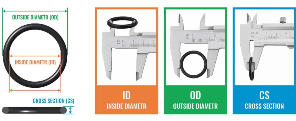
A conventional O-ring is primarily identified by two free-state dimensions:
- Inside diameter (ID): the diameter of the opening through the center of the O-ring.
- Cross-section (CS): the diameter or thickness of the circular rubber section.
The outside diameter can then be calculated from the two dimensions:
OD = ID + 2 × CS
For example, if an O-ring has an ID of 50 mm and a cross-section of 3.53 mm:
OD = 50 + (2 × 3.53) = 57.06 mm
This simple equation is useful for checking measurements, but it should not be used as a substitute for verifying the actual standard designation. Standard O-ring systems use defined dimensional series and tolerances.
Common systems include AS568 in the United States, ISO 3601 internationally, and JIS B 2401 for Japanese applications. Many industrial O-rings are also supplied according to manufacturer-specific or application-specific specifications.
AS568, ISO 3601, and Metric O-Ring Sizes
One of the most common causes of ordering mistakes is assuming that every O-ring described as “metric” or “standard” belongs to the same dimensional system.
AS568 uses dash numbers to identify standard sizes. The series corresponds to different nominal cross-sections. Typical AS568 cross-sections include approximately 1.78 mm, 2.62 mm, 3.53 mm, 5.33 mm, and 6.99 mm, although the complete standard contains additional dimensional provisions and extended series.
ISO 3601 provides internationally recognized O-ring dimensional requirements and classification. In many cases, AS568 dimensions are closely associated with ISO 3601 Class A dimensions, but engineers should never assume interchangeability merely because two dimensions look similar.
| Sizing System | Typical Identification | Typical Use | Important Consideration |
|---|---|---|---|
| AS568 | Dash number such as -214 | North American industrial and hydraulic applications | Verify dash number and dimensional tolerance |
| ISO 3601 | ISO size designation | International industrial applications | Check class, dimensions, and application requirements |
| JIS B 2401 | P, G, V and related series | Japanese equipment and machinery | Do not substitute by nominal metric diameter alone |
| Custom | Drawing or supplier designation | Special machinery and non-standard grooves | Groove geometry becomes especially important |
The Correct Way to Measure an O-Ring
When the original O-ring is available, measure it carefully before attempting identification. Use clean measuring equipment and avoid excessive compression of the rubber during measurement.
Step 1: Inspect the O-Ring Before Measuring
Look for flattening, swelling, cuts, extrusion damage, cracking, surface hardening, compression set, and unusual changes in color or texture. A used O-ring may no longer represent its original dimensions.
A seal exposed to heat can experience permanent deformation. A seal exposed to incompatible fluid can swell. A seal subjected to pressure extrusion can develop a damaged edge. Therefore, measurements taken from a heavily damaged O-ring should be treated as approximate evidence rather than definitive dimensional information.
Step 2: Measure the Cross-Section
Place the O-ring on a clean, flat surface and measure the circular cross-section using a suitable caliper or micrometer. Do not squeeze the O-ring aggressively because elastomers deform under measurement force.
Measure several locations around the circumference. If the readings vary substantially, the O-ring may have suffered compression set, swelling, wear, or mechanical damage.
Expert tip: Never rely on one measurement from one location. Take multiple measurements and compare them with the nearest standard cross-section.
Step 3: Measure the Inside Diameter
For a loose O-ring, measure the inside diameter without stretching it. Large O-rings can be measured by placing them flat and taking several diameter measurements at different orientations.
If the O-ring has become permanently distorted, measure more than one axis. An apparently circular O-ring may have become oval after prolonged installation.
Step 4: Calculate the Outside Diameter
Use the measured ID and cross-section to calculate the expected OD. This provides an additional dimensional check.
For example, assume an O-ring measures approximately 30.0 mm ID and 2.65 mm cross-section.
OD = 30.0 + 2 × 2.65 = 35.30 mm
If the calculated OD does not resemble the installed gland geometry, investigate the measurement or determine whether the original seal was a non-standard size.
Why Measuring the Old O-Ring Alone Can Be Misleading
A common maintenance mistake is to assume that the dimensions of a used seal are the dimensions of the original seal. Elastomeric seals are viscoelastic components and their dimensions can change during service.
Temperature, pressure, chemical exposure, compression, installation stretch, and aging can all influence the final shape.
| Observed Condition | Possible Cause | Measurement Risk |
|---|---|---|
| Swollen O-ring | Chemical incompatibility | ID and CS may be larger than original |
| Flattened cross-section | Compression set | Cross-section may appear undersized |
| Oval shape | Installation or long-term deformation | Single ID measurement becomes unreliable |
| Cracked surface | Heat, ozone, aging or incompatible environment | Original geometry may be lost |
O-Ring Size Selection Starts With the Groove
The most reliable way to select a replacement O-ring is to inspect the gland or groove in which it operates.
The groove determines the available volume, squeeze, stretch, clearance, and resistance to extrusion. If the groove is designed for a particular standard O-ring, selecting the corresponding standard size is generally safer than trying to reproduce the dimensions of a damaged seal.
Static Seals
Static applications generally hold two surfaces without significant relative movement. Examples include flange seals, cover seals, threaded connections, hydraulic manifolds, valve bodies, and pressure housings.
Static seals can often tolerate a relatively broad range of squeeze, provided the groove is properly designed and the material remains within its temperature and chemical limits.
Dynamic Seals
Dynamic applications involve reciprocating, oscillating, or rotary movement. Examples include hydraulic pistons, pneumatic cylinders, rotating shafts, and moving actuator components.
Dynamic sealing requires greater attention to friction, lubrication, surface finish, squeeze, extrusion resistance, and heat generation.
Important: A size that works well in a static application may perform poorly in a dynamic application. O-ring selection must consider both dimensions and movement.
Understanding O-Ring Squeeze a
O-ring squeeze is the percentage reduction in the cross-sectional dimension caused by installation in the gland.
A simplified calculation for radial or axial squeeze can be expressed as:
Squeeze % = (Original CS − Installed CS) ÷ Original CS × 100
Suppose an O-ring has a free cross-section of 3.53 mm and the installed gland compresses it to an effective dimension of 3.00 mm.
Squeeze = (3.53 − 3.00) ÷ 3.53 × 100 ≈ 15.0%
This is only a simplified calculation. Real gland design should account for groove dimensions, tolerances, temperature, pressure, deformation, and the specific application. The objective is to maintain enough contact pressure to seal while avoiding excessive friction, compression set, and material damage.
How O-Ring Stretch Affects Size Selection
In many piston and rotary applications, the O-ring is installed over a diameter and therefore experiences circumferential stretch.
Excessive stretch reduces the effective cross-section and can alter the sealing geometry. It may also increase installation stress and complicate assembly.
For example, if a 50 mm nominal ID O-ring is installed over a 51 mm diameter:
Stretch = (51 − 50) ÷ 50 × 100 = 2%
Whether that stretch is acceptable depends on the specific application and gland design. There is no universal stretch percentage that can safely replace proper engineering calculations.
Material Selection Is Part of O-Ring Sizing
Two O-rings with exactly the same dimensions can behave very differently because they are made from different elastomers.
| Material | Typical Strengths | Common Limitations | Typical Applications |
|---|---|---|---|
| NBR | Good mineral-oil resistance, economical | Limited ozone and weather resistance | Hydraulic oil, lubricants, general machinery |
| HNBR | Improved heat, ozone and mechanical resistance | Higher cost than standard NBR | Automotive, refrigeration, demanding oil applications |
| FKM | High-temperature and chemical resistance | Not universally compatible with all chemicals and low-temperature conditions | Automotive, chemical, industrial |
| EPDM | Excellent water, steam and weather resistance | Generally unsuitable for petroleum oils | Water, cooling systems, outdoor applications |
| Silicone | Wide temperature range and flexibility | Lower abrasion and tear resistance | Medical, food, electronics and temperature-sensitive applications |
| FFKM | Exceptional chemical and temperature resistance | Very high cost | Semiconductor, chemical and extreme environments |
These material descriptions are general engineering guidance rather than universal compatibility guarantees. Actual compatibility depends on compound formulation, concentration, temperature, exposure time, pressure, and mechanical conditions.
O-Ring Hardness and Size Selection
Hardness is commonly specified using the Shore A scale for elastomeric O-rings. Common industrial compounds include approximately 70 Shore A, although softer and harder compounds are available.
A softer O-ring can conform well to surface irregularities and may require lower assembly force. A harder compound generally offers greater resistance to extrusion and mechanical damage, but it can require higher assembly force and may be less forgiving of surface imperfections.
Hardness does not determine size. A 70 Shore A O-ring and a 90 Shore A O-ring can have the same nominal dimensions. Hardness is a material property that must be evaluated alongside geometry.
Temperature Can Change the Effective Seal Geometry
Elastomers respond to temperature changes through thermal expansion, changes in modulus, and changes in compression behavior.
At elevated temperatures, rubber generally becomes softer and may be more susceptible to compression set or extrusion. At low temperatures, some compounds become significantly stiffer and less capable of following surface movement.
This means an O-ring that seals at room temperature is not automatically suitable for the actual operating temperature.
Expert selection rule: Always evaluate the O-ring at the application’s actual temperature range—not merely the temperature of the workshop where the seal is installed.
Pressure, Clearance, and Extrusion
High pressure can force an O-ring into the clearance gap between mating components. This phenomenon is called extrusion.
Extrusion risk depends on pressure, material hardness, temperature, clearance, groove geometry, and whether a backup ring is used.
An O-ring that is dimensionally correct can still fail rapidly if the gland clearance is excessive for the pressure and compound hardness.
Typical extrusion damage appears as a thin, torn, or chewed-looking section on one side of the seal. In severe cases, the material can be pulled into the clearance gap and removed from the sealing interface.
How to Identify an Unknown O-Ring
When the package, part number, and drawing are unavailable, use a structured identification procedure.
- Measure the cross-section.
- Measure the inside diameter.
- Calculate the approximate outside diameter.
- Compare the dimensions with recognized standard size charts.
- Determine whether the application uses an inch, metric, or Japanese sizing system.
- Identify the original material if possible.
- Determine hardness when required.
- Review temperature, pressure, fluid, movement, and installation conditions.
For critical equipment, the final selection should be verified against the equipment manufacturer’s drawing, maintenance manual, or engineering specification.
Case Example: Replacing a Hydraulic O-Ring
Case Example — Industry Engineering Scenario: Consider a hypothetical hydraulic manifold where a technician removes an O-ring measuring approximately 24.5 mm ID and 3.4 mm cross-section.
The technician initially searches for an O-ring with an ID close to 24.5 mm and selects a 3.5 mm cross-section metric ring. After assembly, the manifold develops a leak.
The investigation shows that the original groove was designed around a standard inch-series O-ring. The replacement had a similar nominal diameter but a different cross-section and therefore produced inadequate groove fill and squeeze.
The lesson is important: dimensional similarity is not equivalent to functional equivalence.
This is an illustrative engineering example, not a report of a specific customer, factory, or independently measured field failure.
Laboratory Test Example: Verifying O-Ring Dimensions
Laboratory Test Example — Illustrative Procedure: A quality laboratory receives a batch of O-rings specified by a standard size and material specification.
The laboratory conditions the samples under a controlled environment and measures ID and cross-section at multiple locations. The measurements are compared with the applicable drawing and dimensional specification.
For rubber O-rings, ASTM D1414 provides standardized test methods for determining physical properties and changes in properties associated with aging. Such testing can support quality control and engineering characterization.
A suitable laboratory program may additionally include hardness testing, tensile properties, elongation, compression set, fluid immersion, thermal aging, and dimensional stability testing depending on the application.
The purpose of this example is to demonstrate a reasonable engineering verification process. It does not represent actual laboratory results or a fabricated production test report.
Failure Mode Analysis: Why the Correct Size Can Still Leak
| Failure Mode | Typical Cause | Visual Evidence | Corrective Action |
|---|---|---|---|
| Leakage | Insufficient squeeze or damaged sealing surface | No obvious tearing | Check groove and surface finish |
| Extrusion | Excessive clearance or pressure | Torn or nibbed edge | Reduce clearance, increase hardness, or add backup ring |
| Compression set | Long-term compression and heat | Flattened cross-section | Review material and temperature |
| Swelling | Fluid incompatibility | Oversized or soft seal | Select compatible elastomer |
| Cuts | Sharp groove edge or poor installation | Localized cuts | Deburr and improve installation method |
| Twisting | Rotational movement or improper installation | Spiral marks | Review gland, lubrication and assembly technique |
Installation Practices That Protect the Correct O-Ring Size
Even a perfectly specified O-ring can fail during installation.
Before assembly, clean the groove and mating surfaces. Remove metal particles, old seal fragments, dirt, and excessive lubricant. Inspect the groove for burrs, scratches, corrosion, and sharp edges.
When installing an O-ring over threads, splines, ports, or other sharp features, use appropriate installation protection. Never drag the seal across an unprotected sharp edge if doing so can cut or nick the elastomer.
Use a compatible lubricant when permitted by the application. The lubricant should not attack the elastomer or contaminate the working fluid.
Do not use screwdrivers, knives, or sharp metal tools to force an O-ring into a groove unless the tool and procedure are specifically designed to avoid seal damage.
Installation warning: A microscopic cut can become a pressure-driven leakage path. The seal may look acceptable during assembly but fail after the system is pressurized.
Surface Finish and O-Ring Performance
Surface condition is another factor that is often overlooked when identifying replacement sizes.
An O-ring seals by conforming to the mating surfaces under compression. If a surface is excessively rough, the elastomer may not completely fill the surface profile. If a surface is excessively damaged, scratched, or corroded, leakage can occur even with the correct O-ring.
For dynamic seals, surface finish becomes even more important because excessive roughness can increase friction and accelerate wear.
There is no single universal surface-finish value suitable for every O-ring application. The correct requirement depends on whether the seal is static or dynamic, the material, pressure, speed, lubrication, and groove configuration.
How to Order the Right O-Ring
A professional purchase specification should contain more information than “O-ring, 30 mm.”
A useful order description can include:
- Standard or size designation
- Inside diameter
- Cross-section
- Material
- Hardness
- Color, where relevant
- Temperature range
- Fluid or media compatibility
- Applicable industry specification
- Quantity
- Special certification or traceability requirements
For example, a technical specification might identify an O-ring by its applicable standard size, an HNBR compound, nominal Shore A hardness, and required temperature or fluid compatibility rather than simply specifying a visual dimension.
Common O-Ring Measurement Mistakes
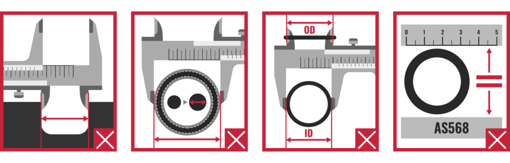
Mistake 1: Measuring Only the Outside Diameter
OD alone cannot uniquely identify an O-ring. Different ID and cross-section combinations can produce similar outside diameters.
Mistake 2: Confusing ID With OD
This is particularly common with small O-rings. Always label measurements clearly before entering them into a size chart.
Mistake 3: Measuring a Swollen Seal
A chemically swollen seal can be substantially different from its original dimensions. Material identification should be performed before ordering a replacement.
Mistake 4: Ignoring Cross-Section
An O-ring with the correct ID but an incorrect cross-section can produce poor squeeze or excessive gland fill.
Mistake 5: Assuming Metric and Inch Sizes Are Interchangeable
Some dimensions may appear nearly identical, but the associated tolerances and groove geometry may not be equivalent.
A Practical O-Ring Identification Worksheet
| Application | ____________________________ |
| Measured ID | ____________________________ |
| Measured Cross-Section | ____________________________ |
| Calculated OD | ____________________________ |
| Standard | AS568 / ISO 3601 / JIS / Custom |
| Material | ____________________________ |
| Hardness | ____________________________ |
| Temperature | ____________________________ |
| Pressure | ____________________________ |
| Fluid | ____________________________ |
Choosing Between Standard and Custom O-Rings
Standard O-rings are normally preferable when the equipment groove has been designed around a recognized standard. Standard sizes offer easier procurement, established dimensional tolerances, broader material availability, and simpler replacement.
Custom O-rings may be appropriate when the equipment has a unique groove, unusually large diameter, specialized cross-section, unusual temperature requirement, or proprietary sealing geometry.
However, creating a custom O-ring should not be the first solution to a measurement problem. Before ordering a custom seal, verify whether the existing groove corresponds to an established standard size.
Why O-Ring Standards Matter for Quality Control
Dimensional standards provide a common technical language between equipment manufacturers, seal suppliers, distributors, and maintenance organizations.
ASTM D1414, for example, establishes test methods for rubber O-rings and addresses physical properties and changes associated with aging. Such standards are useful for engineering verification and quality-control programs.
For production applications, dimensional inspection can be combined with material certification, hardness testing, batch traceability, aging tests, fluid compatibility testing, and other validation methods.
A standard size does not automatically mean a standard performance level. Material compound, manufacturing quality, tolerances, surface condition, and application design remain critical.
Engineering Calculation: Checking Gland Fill
A simplified way to understand gland fill is to compare the approximate cross-sectional area of the O-ring with the available gland volume.
The circular cross-sectional area of an O-ring can be approximated as:
A = π × (CS ÷ 2)2
For a 3.53 mm cross-section:
A ≈ π × (3.53 ÷ 2)2 ≈ 9.79 mm²
This is a geometric approximation rather than a complete gland-fill calculation. Actual elastomer deformation, groove geometry, thermal expansion, pressure, tolerances, and material behavior must be considered in professional seal design.
How Fluid Compatibility Can Change O-Ring Dimensions
Elastomers can absorb fluids. Depending on the polymer and fluid combination, the result may be swelling, shrinkage, softening, hardening, extraction of additives, or degradation.
NBR generally performs well with many petroleum-based oils but is not universally resistant to all fluids. EPDM is highly useful for water and many polar fluids but is generally unsuitable for petroleum oils. FKM is often selected for demanding high-temperature and chemical environments, while silicone is used where temperature flexibility and certain cleanliness requirements are important.
Compatibility charts are valuable starting points, but laboratory testing may be necessary for critical applications because actual performance depends on the specific compound and operating conditions.
Expert Tips for Getting O-Ring Size Right the First Time
Tip 1: Measure both ID and cross-section.
Tip 2: Measure several locations instead of relying on one reading.
Tip 3: Inspect the groove whenever possible.
Tip 4: Identify the material separately from the size.
Tip 5: Check temperature, pressure, fluid, and movement before approving a replacement.
Tip 6: Use a recognized size standard instead of guessing from appearance.
Tip 7: Do not assume a used O-ring retains its original dimensions.
When Should You Replace the Entire Seal Specification?
If an O-ring has failed repeatedly despite apparently correct dimensions, replacing it with another seal of the same size may simply reproduce the same problem.
Repeated failures should trigger a broader investigation.
- Is the material compatible with the fluid?
- Is the hardness appropriate?
- Is the groove correctly machined?
- Is the squeeze appropriate?
- Is clearance excessive under pressure?
- Is the surface finish appropriate?
- Is the seal being twisted during installation?
- Is the operating temperature outside the compound’s useful range?
- Is the equipment experiencing unexpected pressure spikes?
- Is the O-ring exposed to incompatible cleaning chemicals?
This approach is particularly important in hydraulic, pneumatic, automotive, chemical-processing, refrigeration, medical, food-processing, and industrial equipment.
The Difference Between Replacement and Engineering Selection
A replacement task asks: “What seal was originally installed?”
An engineering selection asks: “What seal will reliably perform in this application?”
The two questions are not always identical.
If the original seal was incorrectly specified, replacing it with an identical part may preserve the original problem. Conversely, changing the size without understanding the gland can create a new failure.
The best approach is therefore to combine dimensional identification with application analysis.
A Complete O-Ring Selection Checklist
Before placing an order, confirm all of the following:
- ☑ O-ring ID verified
- ☑ Cross-section verified
- ☑ Standard designation identified
- ☑ Groove dimensions checked where possible
- ☑ Static or dynamic application identified
- ☑ Pressure range confirmed
- ☑ Temperature range confirmed
- ☑ Fluid compatibility confirmed
- ☑ Material selected
- ☑ Hardness selected
- ☑ Extrusion risk evaluated
- ☑ Installation method reviewed
- ☑ Surface condition inspected
- ☑ Required certifications identified
- ☑ Supplier drawing or technical specification reviewed
Frequently Asked Questions About O-Ring Sizes
1. How do I know what size O-ring I need?
Measure the free-state inside diameter and cross-section, then compare both dimensions with the applicable AS568, ISO 3601, JIS, metric, or manufacturer-specific size system. If possible, inspect the groove because the gland geometry provides stronger evidence than a damaged used seal.
2. Can I use a metric O-ring instead of an AS568 O-ring?
Sometimes dimensions may be close enough for a particular design, but they should not be considered automatically interchangeable. Compare the actual ID, cross-section, tolerances, groove geometry, squeeze, pressure, and application requirements before substituting one size system for another.
3. Is O-ring OD enough to identify the size?
No. Outside diameter alone cannot uniquely identify an O-ring. The two primary free-state dimensions are ID and cross-section. OD can be calculated as ID plus twice the cross-section.
4. Why does an O-ring with the correct dimensions still leak?
Possible causes include incorrect material, inadequate squeeze, excessive clearance, extrusion, compression set, incompatible fluid, temperature-related degradation, poor surface finish, installation damage, twisting, pressure spikes, or an incorrectly designed groove.
5. Should I measure the old O-ring or the groove?
Ideally, measure both. The old O-ring provides useful identification information, but the groove establishes the actual sealing geometry. If the old seal is swollen, flattened, stretched, cracked, or otherwise damaged, groove dimensions and the equipment specification should receive greater weight.