Engine Valve Cover Gasket Seal
Categories
Auto Oil Seal
- Auto Oil Seal
- TOYOTA Oil Seal
- Nissan/Honda oil seal
- Isuzu Oil Seal
- MITSUBISHI/FUSO Oil Seal
- SUZUKI Oil Seal
- HYUNDAI/KIA Oil Seal
- HINO Oil Seal
- Ford / Chevrolet Oil Seal
- Peugeot Oil Seal
- VW/Iveco Oil Seal
- LADA/VAZ Oil Seal
- Caterpillar Oil Seal
- MAZDA Oil seals
- BENZ Oil Seal
- VOLVO Oil Seal
- BPW Oil Seal
- MAN oil Seals
- RENAULT Oil Seals
- SCANIA Oil Seal
- MACK Oil Seal
- DAF Oil Seals
- PERKINS Oil Seal
Motorcycle Oil Seal
Agricultural Machine Oil Seal
Construction Machinery Oil Seal
Truck Wheel Hub Oil Seal
Cassette Wheel Hub Oil Seal
Power Steering Oil Seal and Kit
Hydraulic Pump Oil Seal
JCB SEAL KIT
Concrete Mixer Gearbox Oil Seal
Wheel Cylinder Brake Cup Seal
Engine Valve Cover Gasket Seal
- Valve Stem SealAuto Oil Seal
- Valve Cover Gasket
Bonded Seals
End Cover Cap Seals
Speak with a Product Expert
Please contact our professional sales team to discuss your application needs. We have dedicated staff available to answer your calls Monday through Friday, from 8:30 AM to 6:00 PM Beijing time.
New Customers:
+86 18730921709
Existing/Repeat Customers:
Email:sales@kodaseal.com
NEWS
How much does it cost to replace a transmission seal?
Valve Cover Gasket-How Much Do You Know
What are the applications of Yellow O-Ring Kits?
What is AFLAS® Rubber?
Engine Valve Cover Gasket Seal
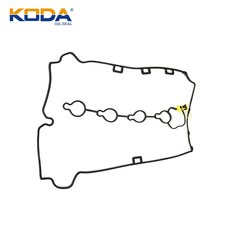
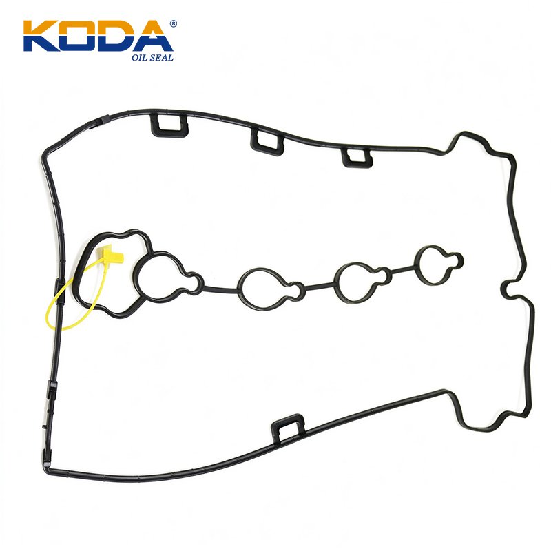
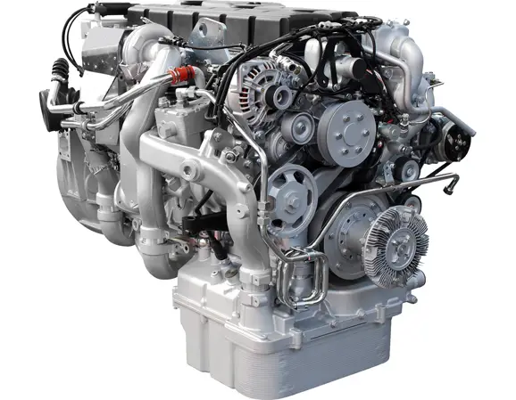
An Engine Valve Cover Gasket Seal is a critical sealing component installed between the engine cylinder head and the valve cover. Its primary function is to prevent engine oil from escaping from the upper engine compartment while maintaining a reliable seal under continuous exposure to heat, vibration, oil splash, pressure fluctuations, and repeated thermal cycling. Although it is relatively small compared with other engine components, its performance directly affects engine cleanliness, lubrication reliability, maintenance costs, and long-term operating stability.
If you have questions about Engine Valve Cover Gasket Seal, please contact us!
SHOW MORE
Modern automotive engines operate under demanding conditions. The valve cover is exposed to elevated temperatures from the cylinder head, while crankcase ventilation systems create changing internal pressure conditions. At the same time, the gasket must accommodate dimensional variations, thermal expansion, surface irregularities, and mechanical movement between mating components. A properly engineered valve cover gasket seal must therefore provide consistent compression, oil resistance, elasticity, and dimensional stability throughout its service life.
ENGINEERING INSIGHT: A valve cover gasket does not prevent leakage simply by being compressed as tightly as possible. Reliable sealing depends on the correct gasket profile, controlled compression, material compatibility, surface condition, and fastening torque. Excessive bolt tightening can cause gasket deformation, extrusion, cracking, or permanent compression set.
What Is an Engine Valve Cover Gasket Seal?
An engine valve cover gasket seal is a shaped sealing element designed to fit between the valve cover and cylinder head. It follows the perimeter of the valve cover and, depending on engine design, may include additional sealing sections around spark plug tubes, camshaft openings, bolt holes, and other structural features.
Its main functions include:
- Oil containment: Prevents lubricating oil from leaking out of the valve cover assembly.
- Environmental protection: Reduces the entry of dust, moisture, and external contaminants into the upper engine area.
- Vibration absorption: Accommodates small relative movements between the valve cover and cylinder head.
- Thermal compensation: Maintains sealing contact during heating and cooling cycles.
- Pressure accommodation: Maintains sealing performance under normal crankcase pressure fluctuations.
Unlike a cylinder head gasket, a valve cover gasket does not normally contain combustion pressure. Its design requirements are primarily related to oil resistance, low-pressure sealing, temperature endurance, compression recovery, and dimensional accuracy.
Typical Valve Cover Gasket Configurations
| Configuration | Construction | Typical Application |
|---|---|---|
| Perimeter gasket | Continuous molded sealing profile | Conventional valve covers |
| Molded rubber gasket | Precision-shaped elastomer | Modern automotive engines |
| Rubber-coated fiber | Reinforced fiber with elastomer coating | Selected high-temperature applications |
| Cork-rubber composite | Cork particles bonded with rubber | Traditional and performance engines |
| Carrier-supported gasket | Molded rubber with rigid supporting structure | Applications requiring controlled positioning and compression |
Materials Used in Engine Valve Cover Gasket Seals
Material selection is one of the most important factors determining gasket performance. A suitable material must withstand prolonged contact with engine oil, elevated operating temperatures, oxidation, compression stress, and repeated thermal cycling.
Silicone Rubber (VMQ)
Silicone rubber is widely used in molded automotive sealing components because of its excellent flexibility and resistance to high and low temperatures. It maintains elasticity across a broad temperature range and can accommodate irregularities in mating surfaces when correctly designed.
Typical characteristics include:
- Good high-temperature and low-temperature flexibility.
- Excellent resistance to ozone and weathering.
- Good compression recovery when an appropriate compound is selected.
- Available in different hardness grades and molded profiles.
- Oil compatibility varies significantly with formulation and engine fluid chemistry.
Silicone should not automatically be considered the best option for every engine oil application. Standard VMQ compounds can exhibit swelling or deterioration in certain oils and additives. Oil-resistant grades and application-specific testing are essential.
Fluoroelastomer (FKM)
FKM is a high-performance elastomer offering excellent resistance to many petroleum-based oils, fuels, lubricants, and aggressive chemicals. It is particularly useful in demanding applications where elevated temperatures and chemical exposure occur simultaneously.
Its advantages include excellent oil resistance, low permeability compared with many conventional elastomers, and good thermal aging performance. However, FKM generally has a higher material cost and may require more specialized molding and processing conditions.
Nitrile Rubber (NBR)
NBR is a widely used oil-resistant elastomer suitable for many conventional sealing applications. Its acrylonitrile content influences the balance between oil resistance, flexibility, and low-temperature performance.
Advantages include:
- Good resistance to mineral oils and petroleum-based lubricants.
- Good mechanical strength and abrasion resistance.
- Relatively economical raw material cost.
- Suitable for many standard automotive sealing applications.
Its principal limitation is temperature endurance. Conventional NBR formulations may harden or lose elasticity under prolonged exposure to elevated temperatures.
Hydrogenated Nitrile Rubber (HNBR)
HNBR is produced by hydrogenating the polymer backbone of nitrile rubber. This improves resistance to heat, oxidation, and certain chemical environments while retaining useful oil resistance.
For valve cover gasket applications involving demanding thermal conditions, HNBR can offer a useful balance between mechanical durability and oil compatibility. Actual performance depends on compound formulation, cure system, hardness, and operating conditions.
Cork-Rubber and Reinforced Composite Materials
Cork-rubber composites combine the compressibility of cork with the flexibility and resilience of rubber. They are particularly useful in certain traditional engine designs where a thicker gasket or greater conformability is required.
Reinforced fiber materials can also provide structural stability and resistance to deformation. Their suitability depends on the coating, reinforcement, temperature exposure, and oil compatibility.
Material Comparison for Valve Cover Applications
| Material | Indicative Temperature Range | Oil Resistance | Main Advantage |
|---|---|---|---|
| NBR | -30 to +100°C | Good to excellent | Cost-effective oil resistance |
| HNBR | -30 to +150°C | Good to excellent | Improved heat and aging resistance |
| FKM | -20 to +200°C | Excellent for many oils | Chemical and thermal resistance |
| VMQ Silicone | -60 to +200°C | Formulation-dependent | Wide temperature flexibility |
| EPDM | -40 to +120°C | Poor for petroleum oils | Weather and ozone resistance |
Important engineering note: The temperature ranges above are indicative screening values for common elastomer families, not guaranteed continuous service limits for every compound. Actual limits depend on formulation, exposure duration, oil chemistry, mechanical stress, and manufacturer specifications. EPDM is generally unsuitable for direct contact with conventional petroleum-based engine oil.
For additional material selection information, consult the elastomer service temperature reference chart.
Hardness, Compression, and Mechanical Performance
Hardness is an important parameter in valve cover gasket design because it influences deformation under clamping force, sealing contact pressure, handling stability, and long-term compression behavior.
Elastomer hardness is commonly measured using Shore A durometer testing in accordance with ASTM D2240. Typical automotive molded rubber gasket compounds may fall within approximately 50–80 Shore A, although the appropriate value depends on gasket geometry and application requirements.
Typical Hardness Selection Considerations
| Hardness | General Behavior | Design Consideration |
|---|---|---|
| 50–60 Shore A | Relatively soft and conformable | May require better extrusion control |
| 60–70 Shore A | Balanced flexibility and support | Useful starting range for development |
| 70–80 Shore A | Greater resistance to deformation | Requires suitable sealing geometry and clamp load |
Hardness alone cannot predict sealing performance. Two compounds with identical Shore A hardness may exhibit significantly different compression set, tensile strength, elongation, oil swelling, and thermal aging behavior.
Understanding Compression Ratio
For a gasket with a known initial thickness, the nominal compression percentage can be calculated using:
Compression Ratio Formula
Compression (%) = [(Original Thickness − Installed Thickness) / Original Thickness] × 100
For example, consider a molded gasket with an initial thickness of 4.0 mm. If the designed installed thickness is 3.2 mm:
Compression = [(4.0 − 3.2) / 4.0] × 100 = 20%.
This 20% value is an illustrative calculation, not a universal valve cover gasket specification. The correct compression must be established through the original equipment design, gasket cross-section, material characteristics, and mechanical limitations of the cover.
Over-compression can cause permanent deformation, while insufficient compression may result in inadequate contact pressure and oil leakage.
Thermal Conductivity and Temperature Resistance
Thermal performance is not determined by maximum temperature resistance alone. A valve cover gasket must retain sufficient elasticity after repeated heating and cooling cycles while maintaining its original sealing profile.
Thermal conductivity describes how readily heat passes through a material. Elastomers generally have relatively low thermal conductivity compared with metals. Depending on the formulation and reinforcement, typical unfilled elastomers have thermal conductivity values broadly around 0.15–0.30 W/(m·K). These are indicative material-family values, not certified specifications for a particular gasket compound.
Low thermal conductivity can reduce heat transfer through the gasket itself, but it does not eliminate thermal aging. Long-term exposure to heat can accelerate oxidation, crosslink changes, hardening, loss of elasticity, and compression set.
Factors Affecting Thermal Durability
- Continuous operating temperature and peak temperature exposure.
- Duration of exposure and number of thermal cycles.
- Engine oil formulation and oxidation products.
- Elastomer polymer type and curing system.
- Compression stress and gasket cross-sectional design.
- Contact with nearby exhaust components.
Expert recommendation: When selecting a material for an engine operating close to its thermal limits, evaluate heat aging, compression set, and oil immersion performance together. A material with a high advertised maximum temperature may still fail if it has inadequate oil compatibility or poor compression recovery.
Applicable ASTM and ISO Standards
International standards provide a consistent framework for evaluating rubber materials, dimensions, mechanical properties, and quality requirements. However, there is no single universal ASTM or ISO standard that defines every design requirement for every engine valve cover gasket.
ASTM D2000 – Automotive Rubber Classification
ASTM D2000 establishes a classification system for vulcanized rubber products used in automotive applications. It categorizes rubber materials according to heat resistance and resistance to swelling in oil, together with additional specified property requirements.
It is useful when defining rubber compound requirements for automotive sealing components. Buyers should specify the appropriate material designation and supplementary properties rather than relying solely on a generic material name.
Official reference: ASTM D2000 – Standard Classification System for Rubber Products in Automotive Applications.
ASTM D2240 – Rubber Hardness Testing
ASTM D2240 describes the durometer method for determining indentation hardness of rubber and other elastomeric materials. Shore A is commonly used for relatively flexible gasket compounds.
Testing should control specimen thickness, surface condition, measurement location, and reading time. Hardness results should be compared using consistent test conditions.
ASTM D395 – Compression Set
ASTM D395 provides methods for determining the compression set of rubber materials. This property is particularly relevant to valve cover gaskets because prolonged compression and elevated temperatures can reduce the material’s ability to recover its original dimensions.
A high compression set may indicate reduced sealing recovery after long-term service. However, compression set results must be interpreted together with the actual gasket design and application conditions.
ISO 3601 – O-Ring Dimensional and Material References
ISO 3601 is an important international standards series for O-rings, including dimensions, tolerances, and elastomeric material specifications. It is relevant when a valve cover assembly uses separate O-ring-style seals, such as spark plug tube seals or circular sealing elements.
For standard O-ring identification and dimensional reference, consult the O-Ring Size and International Dimensional Chart.
It is important to distinguish between O-ring standards and perimeter valve cover gasket specifications. ISO 3601 should not be treated as a direct dimensional standard for an entire custom-shaped valve cover gasket.
Typical Applications and Operating Environments
Engine valve cover gasket seals are used across a wide range of internal combustion engine configurations. Although the basic sealing function remains similar, the actual design and material requirements vary according to engine architecture.
Passenger Vehicles
Passenger car engines commonly use molded silicone, NBR-based compounds, HNBR, or application-specific composite gaskets. Compact engine compartments and plastic valve covers make dimensional stability and controlled compression especially important.
Commercial Vehicles and Diesel Engines
Commercial diesel engines may experience prolonged operating periods, higher vibration exposure, and demanding thermal conditions. Gaskets must maintain sealing performance during extended operation and repeated maintenance cycles.
Performance and Motorsport Engines
High-performance engines may experience increased crankcase pressure, elevated temperatures, and more severe vibration. Reinforced gasket carriers, molded sealing beads, and application-specific high-performance elastomers can improve reliability.
Industrial Engines and Generators
Industrial engines often operate for long periods under relatively stable loads. Long-term thermal aging, compression retention, and compatibility with the specified lubricant are therefore important selection considerations.
Common Valve Cover Gasket Failure Modes
Understanding failure mechanisms helps technicians, maintenance teams, and component manufacturers identify the actual cause of leakage rather than repeatedly replacing the gasket without addressing the underlying problem.
Compression Set and Material Hardening
Continuous compression at elevated temperatures can gradually reduce gasket recovery. The material may become harder and less capable of maintaining sealing contact after thermal cycling.
Typical symptoms: Oil seepage along the gasket perimeter, particularly around corners and bolt locations.
Oil-Induced Swelling
When an elastomer is chemically incompatible with engine oil or its additives, it may absorb fluid and increase in volume. Excessive swelling can distort the sealing profile and create installation difficulties.
Typical symptoms: Enlarged gasket dimensions, softening, surface deterioration, and displacement from the sealing groove.
Excessive Bolt Torque
Overtightening can locally crush the gasket, distort a plastic valve cover, damage bolt bosses, or create uneven sealing pressure. Tightening force should always follow the vehicle manufacturer’s specified torque and sequence.
Incorrect Installation
A twisted gasket, contaminated sealing surface, displaced tube seal, or excessive liquid sealant can interrupt the intended sealing contact. Incorrect RTV application may also create excess material that enters the engine.
Valve Cover Distortion or Cracking
Plastic covers may develop cracks or distortion, while stamped metal covers may have bent sealing flanges. Even a correctly manufactured replacement gasket cannot reliably compensate for severe mechanical damage.
Failure Mode Analysis Table
| Failure Mode | Probable Cause | Recommended Corrective Action |
|---|---|---|
| Oil seepage | Insufficient compression | Verify gasket dimensions and fastening torque |
| Gasket cracking | Thermal aging or chemical attack | Review elastomer selection |
| Gasket extrusion | Excessive compression or poor groove design | Review cross-section and compression limits |
| Dimensional swelling | Poor oil compatibility | Conduct oil immersion testing |
| Localized leakage | Uneven flange or damaged sealing surface | Inspect cover flatness and surface condition |
| Spark plug well oil contamination | Failed tube seals | Replace tube seals and inspect installation |
Installation Procedures and Professional Maintenance Tips
Correct installation is just as important as material quality. Even a high-performance gasket can leak when the mating surfaces are contaminated, the cover is distorted, or the fastening procedure is incorrect.
Step 1: Remove the Existing Gasket
Remove the valve cover according to the vehicle manufacturer’s service procedure. Carefully remove the old gasket, bolt grommets, and spark plug tube seals where applicable. Avoid scratching aluminum or damaging plastic sealing surfaces.
Step 2: Clean and Inspect the Sealing Surfaces
Remove old gasket material, oil deposits, and contaminants. Use a suitable cleaning product that will not damage the cover or cylinder head. Ensure that the sealing grooves and bolt holes are clean and dry.
Step 3: Inspect the Valve Cover
Check for cracks, deformation, damaged bolt holes, and irregular sealing flanges. Pay particular attention to plastic valve covers, which can become brittle after prolonged heat exposure.
Step 4: Position the New Gasket
Install the gasket into its designated groove or locating structure. Ensure that it sits evenly without twisting, stretching, or becoming trapped between components. Replace associated tube seals and grommets when required.
Step 5: Apply RTV Only Where Specified
Some engines require a small amount of RTV silicone sealant at specified joints, such as camshaft cap corners or transitions between the cylinder head and timing cover.
Do not automatically apply RTV around the entire gasket. Many molded rubber gaskets are designed to be installed clean and dry. Excess sealant may interfere with gasket positioning and can enter oil passages.
Step 6: Tighten According to Manufacturer Specifications
Install the valve cover and tighten the fasteners using the specified sequence and torque. Where the manufacturer’s procedure does not specify an alternative sequence, a center-outward pattern may be appropriate, but the actual service manual always takes precedence.
Do not use a universal torque value for all engines. Fastener diameter, thread engagement, cover material, gasket geometry, and compression limiters differ considerably between applications.
PROFESSIONAL INSTALLATION TIP: After installation, inspect the perimeter for displacement and confirm that all associated seals are correctly positioned. Following the manufacturer’s recommended inspection procedure, check for leakage after the engine reaches normal operating temperature. Never retighten fasteners beyond the specified torque to compensate for a leaking gasket.
Laboratory Test Example: Evaluating Valve Cover Gasket Quality
For manufacturers and automotive component buyers, laboratory testing helps verify that a valve cover gasket can withstand its intended service environment. A useful qualification program should combine material testing with component-level sealing evaluation.
Example Laboratory Evaluation Plan
The following is an illustrative engineering test plan. It is not a report of an actual factory test or certified product performance result.
| Test Item | Reference Method | Purpose |
|---|---|---|
| Hardness | ASTM D2240 | Evaluate material hardness consistency |
| Compression set | ASTM D395 | Evaluate deformation recovery |
| Tensile properties | ASTM D412 | Measure tensile strength and elongation |
| Heat aging | ASTM D573 | Evaluate thermal aging effects |
| Oil immersion | ASTM D471 | Evaluate fluid-induced property changes |
A laboratory may use the following illustrative sequence:
- Measure the original dimensions, hardness, mass, and mechanical properties of representative specimens.
- Expose specimens to the specified engine oil under controlled temperature and duration conditions.
- Measure changes in mass, volume, hardness, and dimensions after immersion.
- Conduct heat-aging evaluation using a temperature and duration defined by the product specification.
- Measure compression set and compare the results against the agreed acceptance criteria.
- Install complete gasket samples in a representative valve cover assembly and conduct a controlled leakage evaluation.
Acceptance limits must be established from the application requirements, OEM specifications, material design, and agreed customer quality standards. A laboratory result from a rubber test specimen alone does not prove that the complete gasket assembly is leak-free.
Engineering Case Example: Diagnosing Repeated Valve Cover Oil Leakage
Case type: Illustrative engineering scenario based on common automotive sealing failure mechanisms. This is not a documented customer case or a verified field-service report.
A hypothetical four-cylinder gasoline engine develops oil leakage around the rear corner of its valve cover after a replacement gasket has been installed. The replacement component appears dimensionally correct, and no obvious material cracks are visible.
Initial Observations
- Oil residue is concentrated near one rear sealing corner.
- The majority of the gasket perimeter remains dry.
- The valve cover uses a molded rubber gasket.
- There is no obvious external damage to the replacement gasket.
Investigation
The technician removes the cover and inspects the sealing surfaces. The investigation identifies three possible contributing factors: a small amount of old sealant remains at the corner joint, the gasket is slightly displaced from its locating groove, and one fastening point shows evidence of uneven clamping.
Corrective Measures
The sealing surface is cleaned, the gasket is correctly repositioned, and the cover is inspected for flange deformation. The specified RTV application is followed at the designated joint, and the fasteners are tightened using the engine manufacturer’s prescribed sequence and torque.
Engineering conclusion: A localized oil leak does not necessarily indicate an inferior elastomer compound. Installation errors, surface contamination, cover distortion, and uneven compression can produce the same symptoms. Root-cause analysis should therefore consider both material properties and assembly conditions.
How to Select the Right Engine Valve Cover Gasket Seal
Choosing the correct replacement gasket requires more than matching the approximate length and shape. The gasket must be compatible with the engine architecture and its actual operating environment.
Selection Checklist for Buyers and Engineers
- Vehicle compatibility: Confirm engine code, model year, cylinder configuration, and OEM or aftermarket part number.
- Material selection: Evaluate oil compatibility, operating temperature, and thermal aging resistance.
- Hardness: Confirm that the selected Shore A hardness matches the required sealing profile and compression conditions.
- Dimensions: Check gasket thickness, cross-section, bolt-hole locations, locating features, and spark plug tube seal dimensions.
- Compression performance: Review compression set and sealing recovery characteristics.
- Mechanical stability: Evaluate extrusion resistance, tensile properties, and dimensional stability.
- Manufacturing quality: Review molding accuracy, flash control, surface defects, and batch consistency.
- Validation: Request material test reports and application-specific leakage test evidence where available.
Questions to Ask a Valve Cover Gasket Manufacturer
For automotive distributors, OEM procurement teams, and aftermarket parts suppliers, the following questions help assess a manufacturer’s technical capabilities:
- Which elastomer compounds are available for the required engine application?
- Can the manufacturer provide material hardness, tensile, and compression set test results?
- How does the manufacturer control dimensional tolerances and molding consistency?
- Are oil immersion and thermal aging evaluations available?
- Can the supplier manufacture custom profiles, reinforced structures, and associated tube seals?
- Does the manufacturer maintain batch traceability and documented quality inspection procedures?
A capable supplier should be able to explain why a particular material and gasket geometry are suitable for the application, rather than simply offering a generic rubber replacement.
Why Manufacturing Quality Matters
The reliability of an engine valve cover gasket seal depends on the interaction between material formulation, mold design, production control, and dimensional inspection.
During manufacturing, important quality control points include:
- Raw material control: Verify polymer identification, compound consistency, and incoming material quality.
- Mixing and curing: Maintain appropriate processing conditions to achieve consistent physical properties.
- Mold precision: Control cavity dimensions, sealing bead geometry, and parting-line quality.
- Dimensional inspection: Verify overall length, width, thickness, cross-section, and locating features.
- Visual inspection: Identify cracks, voids, incomplete filling, flash, and surface contamination.
- Performance verification: Conduct material tests and application-specific sealing evaluations.
- Traceability: Maintain production records and inspection documentation for each manufacturing batch.
For custom automotive sealing projects, early engineering communication is particularly important. Sharing drawings, samples, operating temperatures, lubricant specifications, and installation conditions enables a manufacturer to recommend an appropriate compound and production process.
FINAL ENGINEERING TAKEAWAY
A reliable Engine Valve Cover Gasket Seal is the result of correct material selection, optimized sealing geometry, controlled compression, accurate manufacturing, and proper installation. NBR, HNBR, FKM, silicone, and reinforced composite materials each offer different advantages. The best solution is the one validated against the engine’s actual oil chemistry, thermal conditions, dimensional requirements, and service environment.
Frequently Asked Questions (FAQ)
1. What Is the Best Material for an Engine Valve Cover Gasket Seal?
There is no universally best material. Silicone rubber provides excellent temperature flexibility, NBR offers economical oil resistance, HNBR combines improved heat aging and oil resistance, and FKM provides excellent resistance to many oils and chemicals at elevated temperatures. The correct choice depends on engine design, lubricant compatibility, and operating conditions.
2. What Causes an Engine Valve Cover Gasket to Leak?
Common causes include material hardening, compression set, excessive bolt torque, incorrect installation, oil-induced swelling, contaminated sealing surfaces, and valve cover deformation. Crankcase ventilation problems that create abnormal pressure can also contribute to oil leakage and should be investigated when repeated leaks occur.
3. Can RTV Silicone Be Used on a Valve Cover Gasket?
Yes, but only where specified by the engine manufacturer or gasket supplier. Some applications require a small amount of RTV at corners or joints between different engine castings. Many molded rubber gaskets are designed for clean, dry installation, and applying RTV around the entire gasket may cause sealing problems.
4. How Do You Determine the Correct Hardness of a Valve Cover Gasket?
Hardness is normally evaluated using Shore A testing in accordance with ASTM D2240. Many automotive molded rubber gasket compounds fall within approximately 50–80 Shore A, but this is only an indicative range. The final hardness must be determined by gasket geometry, compression requirements, cover rigidity, material properties, and application validation.
5. How Can I Choose a Reliable Engine Valve Cover Gasket Manufacturer?
Choose a manufacturer with automotive elastomer formulation experience, precision rubber molding capabilities, documented quality control, dimensional inspection equipment, and relevant laboratory testing capabilities. Request material specifications, hardness reports, compression set results, oil resistance evaluations, and evidence of application-specific validation. A reliable manufacturer should also provide technical assistance with custom gasket development and material selection.
 Quick View
OE 12605173 Cylinder Head Valve Cover Gasket
Valve Cover Gasket