
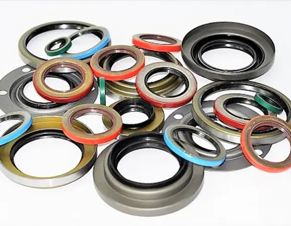
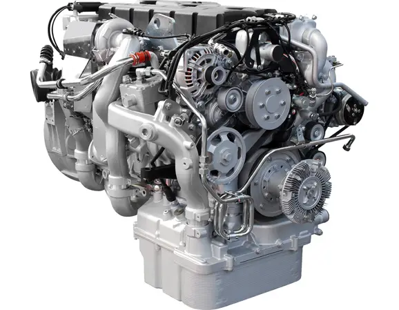

Accurately identifying a metric oil seal requires more than reading the numbers printed on the old component. For maintenance teams, OEM engineers, equipment repair specialists, and industrial distributors, the real objective is to match the replacement seal to the shaft, housing bore, installation depth, operating medium, and service conditions. A seal that appears to have the correct dimensions can still leak if the shaft is worn, the housing fit is incorrect, or the sealing lip design is unsuitable.
This practical guide explains how to measure metric oil seals, which dimensions matter most, how to avoid common measurement errors, and what additional specifications should be confirmed before ordering replacement parts.
✓ Key principle: For replacement selection, measure the shaft diameter, housing bore diameter, and available installation width whenever possible. The old seal is useful for identification, but wear, deformation, and removal damage can make its measured dimensions misleading.
Understand the Three Main Dimensions of a Metric Oil Seal
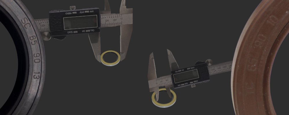
Most conventional metric radial shaft oil seals are described using three nominal dimensions: inner diameter, outer diameter, and width. These dimensions are commonly written in millimetres in the following order: ID × OD × W. Always verify the manufacturer’s catalogue convention because product codes and special seal series may use a different designation system.
| Dimension | Meaning | What it must match |
|---|---|---|
| ID | Inner diameter | Nominal shaft diameter at the sealing track |
| OD | Outer diameter | Nominal housing bore diameter and required press fit |
| W | Width or axial thickness | Available housing depth and the specified seal width |
For example, a conventional seal marked 25 × 47 × 7 mm generally indicates a nominal 25 mm shaft diameter, 47 mm housing bore diameter, and 7 mm seal width. This is a dimensional description, not a complete engineering specification: lip configuration, elastomer compound, case construction, and pressure capability still need to be confirmed.
Why the installation dimensions matter more than the old seal alone
A removed oil seal may have a distorted metal case, a compressed elastomer exterior, a hardened lip, or damage caused by prying it out of the housing. Its present dimensions may therefore differ from its original nominal dimensions. The shaft and housing provide more reliable reference points when they are accessible and can be measured correctly.
For a technical reference, consult the Garlock oil seal measurement guidance and the SKF radial shaft seal product and selection information.
Tools Required for Accurate Measurement
The measuring equipment should suit the size, tolerance, and condition of the component. For a quick workshop identification, a good digital caliper may be sufficient. For engineering verification or a close-tolerance production inspection, use the appropriate calibrated instruments and the manufacturer’s drawing.
- Digital or vernier caliper: Suitable for checking accessible shaft diameters, housing bores within the instrument’s range, and seal width. Confirm that the instrument’s resolution and accuracy meet the required tolerance.
- Outside micrometer: Preferred for measuring shaft diameters when greater accuracy and repeatability are needed.
- Bore gauge or suitable internal measuring instrument: Useful for checking housing bore diameter, taper, and out-of-round conditions.
- Depth gauge: Helps establish the available recess depth and the intended installed position.
- Inspection light and lint-free cloth: Help reveal burrs, contamination, scoring, and damage before measuring.
- Manufacturer’s drawing or catalogue: Essential when the application depends on specific tolerances, seal profiles, or material requirements.
Measurement tip: A digital display showing two decimal places does not guarantee that the measurement is accurate to 0.01 mm. Instrument calibration, contact pressure, surface condition, temperature, and measuring technique all affect the result.
Step-by-Step: How to Measure Metric Oil Seals Correctly
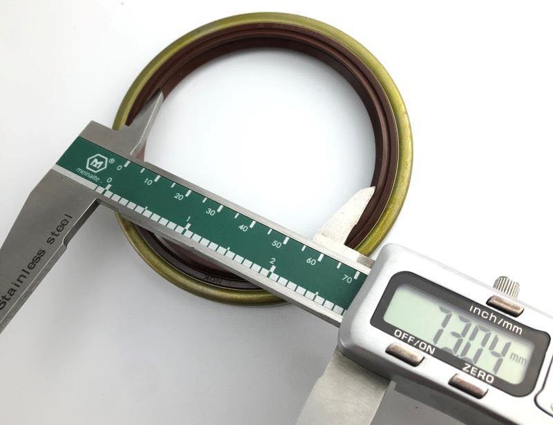
Step 1: Clean the seal and surrounding components
Remove oil residue, dirt, and loose contamination with a suitable cleaning method. Do not use a method that attacks the elastomer or removes identification marks. If the seal has already been removed, inspect it for a bent case, torn lip, displaced spring, or permanent deformation before relying on any measurement.
Also clean the shaft sealing track and the housing bore. Dirt trapped between the measuring instrument and the surface can create a false reading, while a burr can prevent a replacement seal from seating correctly.
Step 2: Measure the shaft diameter
The shaft diameter at the sealing track is the key reference for selecting the seal’s nominal shaft size. Measure the cylindrical surface where the primary lip actually runs, not an adjacent shoulder or an unworn section with a different diameter.
- Identify the contact track left by the old sealing lip.
- Check the shaft at more than one axial position if the track is long enough.
- Take readings in at least two directions, approximately 90 degrees apart, at each relevant position.
- Record the readings rather than immediately rounding them to a standard size.
- Inspect for a wear groove, corrosion, scoring, and surface damage.
If the readings differ noticeably, the shaft may be out of round, tapered, worn, or incorrectly measured. Do not assume that choosing the nearest nominal seal size will compensate for a damaged shaft. The correct response may involve shaft repair, a suitable repair sleeve, or a revised sealing arrangement approved for the application.
Step 3: Measure the housing bore diameter
The housing bore is the cylindrical opening into which the seal’s outside diameter is installed. Where possible, measure the actual bore rather than relying solely on the outside diameter of the removed seal.
- Remove residual sealant, corrosion, and contamination without damaging the bore.
- Inspect the bore entrance for burrs, dents, and installation damage.
- Measure the internal diameter at multiple angular positions.
- Where the bore is deep enough, check at more than one depth to identify taper or local damage.
- Compare the readings with the equipment drawing or the seal manufacturer’s recommended housing tolerance.
Do not automatically treat the measured housing bore as the replacement seal’s exact free-state outside diameter. A press-fit seal generally needs an appropriate interference fit, and the permitted fit depends on the seal construction, housing material, nominal diameter, and design specification.
Step 4: Measure the seal width and installation depth
Measure the old seal’s axial width from the front face to the rear face using a caliper, taking care not to crush a flexible rubber-covered exterior. If the seal is damaged or its width is uncertain, measure the housing recess depth and compare it with the assembly drawing.
Width and recess depth are related but are not always interchangeable. Some designs have a flange, protruding lip, or other geometry that changes how the seal sits in the housing. Confirm whether the drawing specifies nominal seal width, bore depth, or an installed axial position.
Step 5: Record the complete dimensional result
Record all readings in millimetres and label each dimension clearly. A useful inspection note includes:
- Measured shaft diameter and the location of each reading.
- Measured housing bore diameter and measurement depth.
- Available recess depth and required installed position.
- Old seal markings, manufacturer, and any visible part number.
- Seal profile, lip arrangement, case type, and material if known.
- Observed wear, scoring, corrosion, or out-of-round conditions.
This record gives a supplier or engineering team enough context to investigate a suitable replacement instead of relying on three numbers without knowing the operating environment.
How to Measure a Seal When the Markings Are Missing
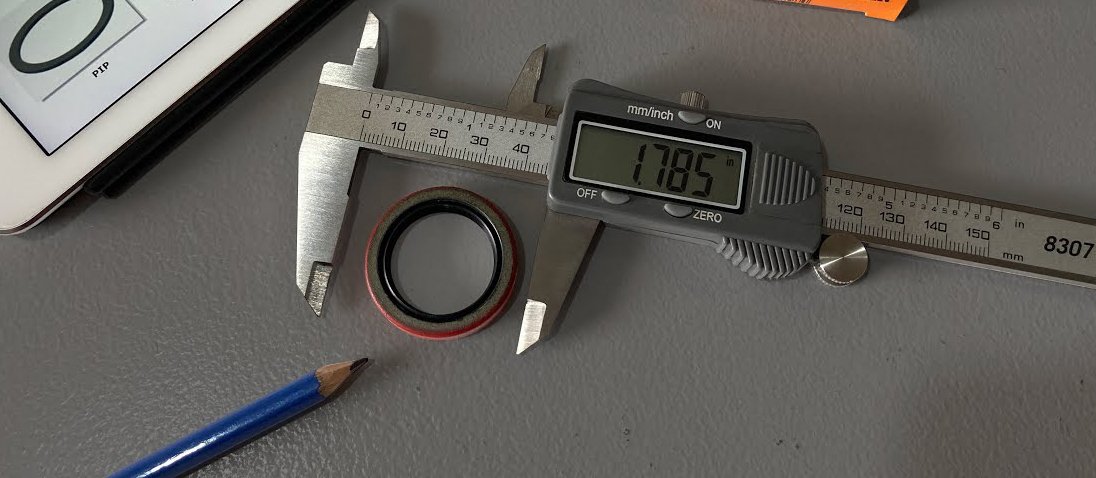
When no size is printed on the seal, start with the machine’s dimensions and documentation. If the seal is already removed, use its dimensions as supporting evidence rather than treating them as definitive.
Measuring the old seal itself
- Outside diameter: Measure carefully across the seal’s exterior. Rubber-covered and metal-cased seals can have different nominal outside-diameter requirements. A suitable diameter tape or specialist measuring method may be preferable when ovality is suspected.
- Width: Measure the axial thickness at several points. Avoid applying excessive force to a flexible outer surface.
- Inside diameter: Use caution. The sealing lip is designed to contact the shaft and may be spring-loaded or flexible. Caliper jaws can stretch, cut, or distort it, producing a misleading reading.
For a spring-loaded radial shaft seal, the relaxed lip opening is not necessarily equal to the nominal shaft diameter. It is generally better to establish the intended shaft size from the shaft itself, the original part number, or a verified manufacturer drawing.
Avoid this common mistake: Do not pull the sealing lip outward to make the inside diameter easier to measure. Stretching the lip or moving its garter spring can alter the component and compromise subsequent identification.
Identify the Seal Profile, Not Just Its Size
Two oil seals can share the same nominal ID, OD, and width but differ significantly in performance. The profile determines how the seal is retained, how the lip contacts the shaft, and whether the assembly provides additional protection against contamination.
| Feature | What to inspect | Why it matters |
|---|---|---|
| Primary sealing lip | Lip geometry, spring, wear, and direction | Controls lubricant retention at the shaft interface |
| Auxiliary dust lip | Presence and clearance of the secondary lip | Helps exclude dust, moisture, and other contaminants |
| Outer case | Rubber-covered, exposed metal, or reinforced construction | Affects retention, bore contact, and installation behaviour |
| Elastomer compound | NBR, FKM, or another specified compound | Determines compatibility with temperature and media |
| Special design features | Flange, auxiliary barrier, special case, or directional lip | May be essential to fit or operating performance |
Do not infer the exact profile from a short marking alone unless the manufacturer’s coding system is confirmed. Letter codes are not universal across all suppliers. Verify the drawing or product catalogue before ordering a functionally different seal.
Metric Oil Seal Markings and Size Notation
Many standard metric oil seals use a three-number size designation, commonly expressed as ID × OD × width. For example, 30 × 52 × 7 mm typically indicates a nominal shaft size of 30 mm, a housing bore size of 52 mm, and a width of 7 mm.
However, some manufacturers list shaft diameter, housing bore diameter, and width in a product designation that includes the seal series and material code. The order and meaning of dimensions should always be checked against the specific catalogue. Never assume that every supplier’s part number follows the same format.
Metric and imperial seals should also be distinguished carefully. A nominal size converted from inches to millimetres may not correspond to an interchangeable standard metric part. For example, a measured value close to a metric size does not prove that the original component was designed to that metric specification.
For examples of manufacturer-specific designation conventions and dimensional data, see the SKF radial shaft seal reference tables and the SKF radial shaft seal product range.
Tolerances: Why a Correct Nominal Size Can Still Fail
Nominal dimensions identify the intended size, but the actual shaft, bore, and seal dimensions are subject to tolerances. A successful fit depends on the permitted dimensional range and the design of the seal, not simply on matching three rounded numbers.
Shaft tolerance and sealing contact
If the shaft is undersized, oversized, tapered, or out of round, the sealing lip may not maintain the intended contact conditions. Excessive interference can increase friction, heat, and wear; insufficient contact can contribute to leakage. Use the shaft tolerance specified by the equipment or seal manufacturer for the actual application.
Housing tolerance and retention
The housing bore must provide the intended retention without damaging the seal during installation. An oversized bore may weaken retention, while an undersized or damaged bore can distort the seal case or make installation excessively difficult. The correct tolerance can depend on whether the outside diameter is rubber-covered or metal-cased.
Surface condition and geometry
Even when dimensions fall within specification, a worn sealing track, sharp housing edge, or damaged bore can cause early failure. Check the manufacturer’s guidance for shaft surface finish, hardness, lead-in chamfer, allowable runout, and alignment. Requirements vary with speed, pressure, media, and seal design.
SKF provides technical dimensional information for radial shaft seals, including housing bore tolerances, in its Industrial Shaft Seals catalogue. Use the relevant table and seal series rather than applying one tolerance universally to every oil seal.
Choose the Correct Material for the Operating Environment
Dimensions alone do not determine service life. The elastomer must be compatible with the lubricant or process fluid, temperature range, speed, and exposure to environmental contaminants. Common materials include nitrile rubber (NBR) and fluoroelastomer (FKM), but the correct choice depends on the compound formulation and operating conditions.
| Material consideration | Questions to confirm |
|---|---|
| NBR | Is the compound suitable for the actual oil, additives, temperature range, and expected service conditions? |
| FKM | Does the selected compound provide the required chemical and thermal resistance for the specific medium? |
| Other elastomers | Are low-temperature flexibility, water exposure, food-contact requirements, or other special conditions involved? |
Material names alone do not guarantee compatibility. Different formulations within the same polymer family can behave differently, and compatibility charts should be treated as screening tools rather than a substitute for the compound manufacturer’s recommendations or application testing.
Before confirming a material, provide the supplier with the fluid name, operating and peak temperatures, rotational speed, pressure conditions, and any cleaning chemicals or washdown exposure. This information is especially important for pumps, gearboxes, agricultural equipment, industrial motors, and vehicle components.
Common Measurement Errors and How to Prevent Them
- Measuring only the removed seal: The old component may be worn or distorted. Verify shaft, bore, and recess dimensions where possible.
- Measuring the wrong shaft location: Measure the actual sealing track, not a nearby shoulder or an unrelated nominal diameter.
- Stretching the sealing lip: Avoid pulling the lip open with caliper jaws. Use the shaft specification or manufacturer data to establish nominal ID.
- Taking only one reading: Multiple readings help reveal ovality, taper, and local damage.
- Ignoring the outer case type: Rubber-covered and metal-cased designs may have different installation requirements even when nominal dimensions appear similar.
- Rounding measurements too early: Preserve the actual readings and compare them with the relevant tolerance specification before deciding on a nominal size.
- Ignoring installation depth: A seal can have the correct ID and OD but still interfere with adjacent components or sit at the wrong axial position.
- Ordering by colour alone: Rubber colour is not a reliable material identification method. Confirm the compound through traceable part data or supplier documentation.
- Overlooking the operating environment: A dimensionally correct seal can fail prematurely if its material, lip design, or speed capability is unsuitable.
Practical purchasing rule: If the measured shaft and bore dimensions disagree with the old seal marking, stop before ordering. Check the original drawing, equipment model, seal series, and possible wear or previous incorrect repairs. Do not force a replacement into a questionable fit.
A Measurement Checklist for Global B2B Buyers and Distributors
For purchasing teams sourcing metric oil seals across multiple suppliers or regions, a standardized inspection record reduces miscommunication and helps prevent avoidable returns. Include both dimensional information and the operating conditions needed for a valid technical recommendation.
- ☑ Confirm whether the equipment uses a metric or imperial seal.
- ☑ Record shaft diameter, housing bore diameter, and recess depth.
- ☑ Record the original seal’s nominal ID × OD × width, if verified.
- ☑ Identify the seal profile, outer case construction, and auxiliary lip arrangement.
- ☑ Confirm the elastomer compound and any metal-case or spring material requirements.
- ☑ Specify the working fluid, temperature range, speed, pressure, and contamination exposure.
- ☑ Document any shaft wear, bore damage, leakage history, or installation constraints.
- ☑ Request a technical drawing, dimensional tolerance data, and traceable part identification for critical applications.
- ☑ Confirm packaging, inspection requirements, quantity, lead time, and applicable quality documentation.
For distributors, it is also useful to maintain a cross-reference record that distinguishes verified equivalents from parts that are only dimensionally similar. Cross-reference decisions should account for profile, material, and performance requirements, not just the three principal dimensions.
When to Request Engineering Support
Seek assistance from the original equipment manufacturer or a qualified seal supplier when the seal operates at high speed, sees pressure beyond a conventional low-pressure oil-retention application, runs in an aggressive fluid, or is installed in a safety-critical assembly. Engineering review is also advisable when the shaft or bore is damaged, the original part number is unavailable, or no standard size matches the measured dimensions.
When requesting a recommendation, provide clear photographs of both sides of the old seal, a side-profile view, all visible markings, measured shaft and bore dimensions, and the application details. Photographs help identify construction, but they cannot replace dimensional verification or material confirmation.
Frequently Asked Questions
FAQ 1: What do the three numbers on a metric oil seal mean?
They commonly indicate inner diameter, outer diameter, and width, in that order, expressed in millimetres. For example, 25 × 47 × 7 mm generally represents a nominal 25 mm shaft, 47 mm housing bore, and 7 mm width. Verify the specific manufacturer’s designation before ordering.
FAQ 2: Can I measure an oil seal with a digital caliper?
Yes. A suitable digital caliper is useful for preliminary identification and checking accessible dimensions. For tighter tolerances, shaft measurements, or production inspection, a micrometer, bore gauge, or other calibrated instrument may be more appropriate. Measuring the flexible sealing lip directly can distort it and produce an unreliable result.
FAQ 3: Should I measure the old seal or the shaft and housing?
Where accessible, prioritize the shaft diameter, housing bore diameter, and available installation depth, then use the old seal markings and measurements as supporting information. Removed seals can be worn, compressed, or damaged, so they should not be the sole reference for replacement selection.
FAQ 4: Why does a replacement oil seal leak even when its dimensions match?
Possible causes include an incorrect lip profile, incompatible elastomer, damaged or worn shaft track, incorrect housing fit, poor installation, excessive runout, unsuitable speed or temperature, and pressure conditions outside the seal’s capability. Check the full application specification rather than assuming the nominal dimensions are the only issue.
FAQ 5: What information should I send a supplier to identify a metric oil seal?
Provide the shaft diameter, housing bore diameter, recess depth, original seal markings, photographs of the seal profile, required lip arrangement, operating fluid, temperature range, rotational speed, pressure conditions, and quantity. For critical equipment, include the original drawing or equipment model and request confirmation of the recommended part and its tolerances.
Need Help Identifying the Right Metric Oil Seal?
Accurate measurements are the starting point for reliable sealing performance. If you are sourcing metric oil seals for maintenance, OEM production, or distribution, prepare the shaft and housing dimensions together with the application conditions before requesting a quotation.
Contact the KODA team with your drawings, part numbers, photographs, or measurement records to discuss suitable seal dimensions, profiles, and material options for your application.
For standards-based work, the ISO 6194-1 standard for rotary shaft lip-type seals specifies nominal dimensions and tolerances for elastomeric lip seals, shafts, and housings. The standard is a useful reference for engineering teams that need a consistent dimensional basis across suppliers.
Proper handling and installation are also important. See ISO 6194-3: Storage, handling and installation for the standard’s scope and guidance.