
Hydraulic kits
Boss, Face & Flange O-Rings
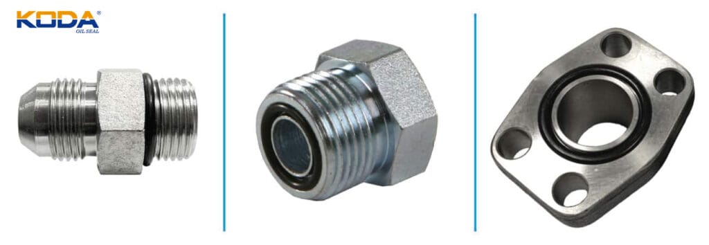
Boss O-Rings, O-Ring Face Seal (ORFS) O-Rings, and SAE Flange O-Rings are engineered specifically for hydraulic fitting systems where high pressure, vibration, and repeated assembly demand a dependable seal. Unlike standard O-rings used in general-purpose glands, these seals are designed to match dedicated fitting standards, ensuring correct compression and long-term sealing performance in hydraulic circuits.
Boss O-Rings (ORB)
O-Ring Face Seal (ORFS)
Flange O-Rings

Understanding the Three Sealing Types
Although all three are used in hydraulic systems, each serves a different connection design.
| O-Ring Type | Typical Fitting | Main Function |
|---|---|---|
| Boss O-Rings (ORB) | Straight thread O-ring Boss fittings | Seal threaded hydraulic ports |
| ORFS O-Rings | O-Ring Face Seal fittings | Create a leak-free metal-to-metal face seal |
| SAE Flange O-Rings | 4-Bolt Code 61 & Code 62 flanges | Seal high-pressure pump, valve, and pipe connections |
Selecting the wrong style—even if dimensions appear similar—can result in insufficient compression and hydraulic leakage.
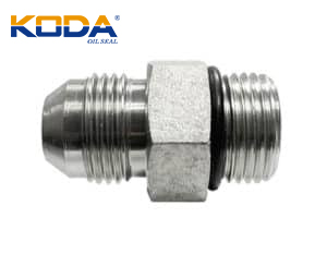
Boss O-Rings (ORB)

Boss O-Rings are installed in SAE straight-thread O-ring Boss (ORB) ports, where the seal is created by compressing the O-ring against a machined port rather than relying on thread sealing.Best suited for: Hydraulic manifolds Pumps Cylinders Valves Industrial fluid power equipmentMost Boss O-Rings correspond to the AS568 900 Series and are commonly manufactured in 90 Shore A NBR for improved extrusion resistance under medium and high pressure.
Boss O-Ring Size Chart
The interactive table below displays the sizes of Boss O-Rings (ORB) and their corresponding specifications. The first column indicates the outer diameter of the pipe corresponding to the O-ring size. The numbers in the second column link to the corresponding size filter page in our online store.
| Tube 0D | AS568 Dash # | CS Inch | ID inch |
|---|---|---|---|
| 3/32 | 901 | 0.056 | 0.185 |
| 1/8 | 902 | 0.064 | 0.239 |
| 3/16 | 903 | 0.064 | 0.301 |
| 1/4 | 904 | 0.072 | 0.351 |
| 5/16 | 905 | 0.072 | 0.414 |
| 3/8 | 906 | 0.078 | 0.468 |
| 7/16 | 907 | 0.082 | 0.53 |
| 1/2 | 908 | 0.087 | 0.644 |
| 9/16 | 909 | 0.097 | 0.706 |
| 5/8 | 910 | 0.097 | 0.755 |
| 11/16 | 911 | 0.116 | 0.863 |
| 3/4 | 912 | 0.116 | 0.924 |
| 13/16 | 913 | 0.116 | 0.986 |
| 7/8 | 914 | 0.116 | 1.047 |
| 1 | 916 | 0.116 | 1.171 |
| 1-1/8 | 918 | 0.116 | 1.355 |
| 1-1/4 | 920 | 0.118 | 1.475 |
| 1-1/2 | 924 | 0.118 | 1.72 |
| 1-3/4 | 928 | 0.118 | 2.09 |
| 2 | 932 | 0.118 | 2.337 |
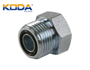
O-Ring Face Seal (ORFS)

ORFS fittings seal by compressing an O-ring between two flat metal faces, creating one of the most reliable hydraulic connections for systems exposed to vibration and pressure cycling.Advantages Virtually eliminates leakage Excellent vibration resistance Easy assembly without thread sealant Suitable for high-pressure hydraulic systems Reduced maintenance requirementsORFS fittings are widely used in construction equipment, agricultural machinery, mobile hydraulics, and heavy-duty industrial systems.
O-Ring Face Seal (ORFS) Size Chart
The table below lists the dimensions of O-ring face seals and their corresponding specifications. The first column corresponds to the ORS pipe diameter, and the numbers with short dashes in the second column link to the corresponding size filter page in our online store.
| ORS Tube Size | Nominal Tube 0D | AS568 Dash # | CS Nominal | ID Nominal | OD Nominal | GS Inch | ID inch |
|---|---|---|---|---|---|---|---|
| -4 | 1/4 | 011 | 1/16 | 5/16 | 7/16 | 0.07 | 0.301 |
| -6 | 3/8 | 012 | 1/16 | 3/8 | 1/2 | 0.07 | 0.364 |
| -8 | 1/2 | 014 | 1/16 | 1/2 | 5/8 | 0.07 | 0.489 |
| -10 | 5/8 | 016 | 1/16 | 5/8 | 3/4 | 0.07 | 0.614 |
| -12 | 3/4 | 018 | 1/16 | 3/8 | 7/8 | 0.07 | 0.739 |
| -16 | 1 | 021 | 1/16 | 15/16 | 1-1/16 | 0.07 | 0.926 |
| -20 | 1-1/4 | 025 | 1/16 | 1-3/16 | 1-5/16 | 0.07 | 1.176 |
| -24 | 1-1/2 | 029 | 1/16 | 1-1/2 | 1-5/8 | 0.07 | 1.489 |
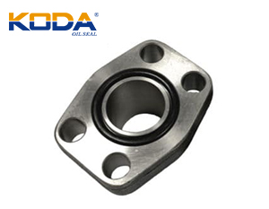
SAE Flange O-Rings

SAE Flange O-Rings are designed for 4-bolt flange connections commonly found on large hydraulic pumps, motors, valves, and pipelines where threaded fittings become impractical.Typical applications include:Hydraulic power units Excavators Mining equipment Injection molding machines Marine hydraulic systemsStandard flange systems generally include:Code 61 – Medium-pressure applications (up to approximately 3,000 PSI) Code 62 – High-pressure applications (up to approximately 6,000 PSI)Using the correct flange class and O-ring size is essential for maintaining sealing integrity.
If you require more information about KODA O-rings, O-ring face seals, or flange O-rings, please call +86 18730921709 or fill out the product inquiry form to get a quote or more information.
Flange O-Ring Size Chart
The interactive table below displays the dimensions and corresponding specifications of flange O-rings. 90-degree hardness nitrile rubber flange O-rings are available in two pressure ratings: No. 61 (maximum pressure resistance 3000 PSI, suitable for standard pressure conditions) and No. 62 (maximum pressure resistance 6000 PSI, suitable for high-pressure conditions). The first column of the table lists the flange dimensions in inches; the numbers with short horizontal lines in the second column are links that will take you to the corresponding size’s filter page on the product page.
| SAE Flange Size | AS568 Dash # | Tubing Dash Size | CS Nominal | ID Nominal | OD Nominal | GS Inch | ID inch |
|---|---|---|---|---|---|---|---|
| 1/2 | 210 | -8 | 1/8 | 3/4 | 1 | 0.139 | 0.734 |
| 5/8 | 212 | -10 | 1/8 | 7/8 | 1-1/8 | 0.139 | 0.859 |
| 3/4 | 214 | -12 | 1/8 | 1 | 1-1/4 | 0.139 | 0.984 |
| 1 | 219 | -16 | 1/8 | 1-5/16 | 1-9/16 | 0.139 | 1.296 |
| 1-1/4 | 222 | -20 | 1/8 | 1-1/2 | 1-3/4 | 0.139 | 1.484 |
| 1-1/2 | 225 | -24 | 1/8 | 1-7/8 | 2-1/8 | 0.139 | 1.859 |
| 2 | 228 | -32 | 1/8 | 2-1/4 | 2-1/2 | 0.139 | 2.234 |
| 2-1/2 | 232 | -40 | 1/8 | 2-3/4 | 3 | 0.139 | 2.734 |
| 3 | 237 | -48 | 1/8 | 3-3/8 | 3-5/8 | 0.139 | 3.359 |
| 3-1/2 | 241 | -56 | 1/8 | 3-7/8 | 4-1/8 | 0.139 | 3.859 |
| 4 | 245 | -64 | 1/8 | 4-3/8 | 4-5/8 | 0.139 | 4.359 |
| 5 | 253 | -80 | 1/8 | 5-3/8 | 5-5/8 | 0.139 | 5.359 |
Material Selection
Choosing the correct elastomer directly affects sealing performance and service life.
| Material | Recommended Environment |
|---|---|
| NBR (Buna-N) | Hydraulic oil, petroleum fluids |
| FKM (Viton®) | High temperature and aggressive chemicals |
| EPDM | Water glycol fluids and outdoor applications |
| HNBR | Heavy-duty hydraulic equipment |
| FFKM | Extreme chemical processing environments |
For most hydraulic systems using mineral oil, 90 Shore A NBR remains the industry standard because it provides an effective balance of sealing performance, wear resistance, and extrusion resistance.
Common Causes of Hydraulic O-Ring Failure
Many sealing failures are not caused by poor-quality O-rings but by incorrect installation or specification.
Avoid these common issues:
- Installing the wrong AS568 series
- Twisting or pinching the O-ring during assembly
- Reusing compressed seals
- Selecting an incompatible rubber compound
- Damaged sealing surfaces or grooves
- Excessive operating pressure without proper backup support
Field experience consistently shows that flange and ORFS fittings will leak if the required O-ring is omitted or incorrectly sized.
Reliable Sealing for High-Pressure Hydraulic Systems
Boss O-Rings, ORFS O-Rings, and SAE Flange O-Rings are purpose-built sealing components that ensure safe, leak-free hydraulic connections under demanding operating conditions. Selecting the correct fitting standard, material, and hardness helps maximize equipment reliability, reduce maintenance costs, and extend the service life of hydraulic systems.