Why O-Ring Extrusion and Spiral Failure Remain Major Causes of Seal Failure
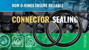
O-rings are among the most widely used sealing components in modern engineering. Their simple design, cost-effectiveness, and versatility make them essential in hydraulic systems, pneumatic equipment, automotive assemblies, aerospace components, industrial machinery, medical devices, and fluid power systems. Despite their reliability, O-rings are not immune to failure. Two of the most common and costly failure modes are extrusion and spiral failure.
When these issues occur, even a high-quality seal can experience leakage, pressure loss, equipment downtime, and expensive repairs. Understanding the root causes of O-ring extrusion and spiral failure is therefore critical for engineers, maintenance professionals, equipment manufacturers, and procurement specialists seeking to maximize seal performance and system reliability.
A properly selected and installed O-Ring can provide years of dependable service. However, preventing premature failure requires a thorough understanding of operating conditions, material selection, groove design, pressure management, and installation best practices.
What Is O-Ring Extrusion?
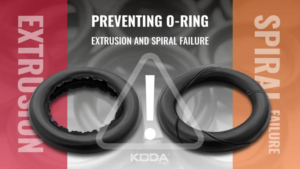
Extrusion occurs when an O-ring is forced into the clearance gap between mating hardware components under pressure. As system pressure increases, the elastomer material deforms and begins flowing into available gaps. Over time, the material becomes pinched, cut, or permanently damaged.
This phenomenon is particularly common in high-pressure hydraulic systems where clearance gaps exceed recommended design limits.
Initially, extrusion may appear as slight deformation along the seal edge. If pressure exposure continues, the O-ring can experience tearing, nibbling, chunking, and ultimately complete sealing failure.
Common Signs of O-Ring Extrusion
✔ Torn seal edges
✔ Nibbling or material loss
✔ Permanent deformation
✔ Pressure leakage
✔ Seal fragments inside the system
What Causes O-Ring Extrusion?
Multiple factors contribute to extrusion-related failures.
Excessive System Pressure
As pressure increases, the sealing force acting on the elastomer also increases. When pressure exceeds the material’s ability to resist deformation, extrusion begins.
Large Hardware Clearance Gaps
Clearance gaps between pistons, rods, cylinders, or housing components create pathways where seal material can be forced under pressure.
Low Durometer Materials
Soft elastomers deform more easily than harder compounds. In high-pressure applications, insufficient hardness often accelerates extrusion.
Elevated Temperatures
Heat reduces elastomer stiffness and increases material flow, making extrusion more likely.
Pressure Spikes
Transient pressure peaks frequently exceed design limits and can damage seals even when average operating pressure appears acceptable.
What Is Spiral Failure in O-Rings?
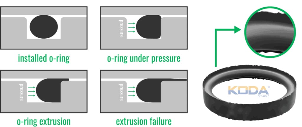
Spiral failure, sometimes called spiral twist failure, is a unique form of seal damage characterized by a helical or corkscrew-shaped cut around the circumference of the O-ring.
Unlike extrusion, spiral failure is primarily associated with dynamic applications involving reciprocating motion. During operation, the seal twists within its groove. As pressure and movement continue, the twisted seal becomes trapped and shears along its circumference.
The resulting damage often resembles a spiral cut that wraps around the O-ring body.
Because spiral failure can occur rapidly and unexpectedly, it remains one of the most difficult seal failures to diagnose without careful inspection.
What Causes Spiral Failure?
Excessive Friction
High friction between the seal and sealing surfaces increases torsional stress during motion.
Rapid Pressure Cycling
Frequent pressure changes can cause the O-ring to shift, twist, and rotate inside the groove.
Improper Groove Design
Grooves that allow excessive seal movement increase the risk of rotational instability.
Insufficient Lubrication
Poor lubrication increases drag forces that contribute to twisting.
High Reciprocating Speeds
Dynamic systems operating at elevated speeds create greater stress on the sealing element.
Why Extrusion and Spiral Failure Are Often Misdiagnosed
Many maintenance teams mistakenly attribute seal failures to material defects rather than application conditions. In reality, most extrusion and spiral failures result from design, installation, or operational factors.
Accurate diagnosis requires evaluating:
Operating pressure
Temperature exposure
Hardware tolerances
Surface finish quality
Lubrication conditions
Material compatibility
Installation procedures
A thorough root cause analysis often reveals opportunities for significant reliability improvements.
How Backup Rings Prevent O-Ring Extrusion
One of the most effective solutions for extrusion prevention is the use of backup rings. These rigid support components are installed adjacent to the O-ring and help prevent elastomer material from entering clearance gaps.
Backup rings are commonly manufactured from PTFE, filled PTFE, nylon, or engineered thermoplastics.
In high-pressure systems, pairing an O-Ring with properly designed backup rings can dramatically increase sealing reliability.
Benefits of Backup Rings
Improved extrusion resistance
Higher pressure capability
Longer seal life
Enhanced reliability
Reduced maintenance costs
Material Selection for Extrusion Resistance
Choosing the correct elastomer compound is critical.
NBR (Nitrile)
Widely used for hydraulic systems and petroleum-based fluids.
FKM (Viton®)
Provides excellent temperature and chemical resistance.
HNBR
Offers improved wear resistance and mechanical strength.
Polyurethane
Excellent for high-pressure applications due to exceptional toughness.
Higher hardness materials generally provide improved extrusion resistance when application conditions allow.
The Importance of Groove Design
Seal performance depends heavily on proper groove geometry.
Optimized groove design controls:
Seal compression
Movement limitations
Pressure distribution
Lubrication retention
Thermal expansion accommodation
Poor groove design increases both extrusion and spiral failure risks regardless of seal quality.
Reducing Spiral Failure Through Proper Lubrication
Lubrication plays a major role in preventing seal twisting. Proper lubrication minimizes friction between the seal and mating surfaces while reducing torsional loads.
Benefits include:
Reduced friction
Lower operating temperatures
Improved seal stability
Reduced wear rates
Longer service life
Many engineers overlook lubrication as a root cause when investigating dynamic seal failures.
Installation Errors That Lead to Premature O-Ring Failure
Even premium sealing materials can fail quickly if installation practices are poor.
Twisted Installation
An O-ring installed with pre-existing twist is significantly more susceptible to spiral failure.
Sharp Edge Damage
Improper installation tools may nick or cut the seal surface.
Contamination During Assembly
Particles trapped within the sealing interface accelerate wear and damage.
Incorrect Compression Levels
Too little compression causes leakage, while excessive compression increases friction and stress.
Emerging Technologies for Preventing O-Ring Failure
Advancements in sealing technology continue to improve O-ring reliability. Modern developments include low-friction coatings, advanced elastomer compounds, finite element seal analysis, predictive maintenance systems, and precision-manufactured backup rings.
These innovations help engineers better predict seal behavior under real-world operating conditions and reduce failure risks before equipment enters service.
Manufacturers increasingly use simulation software to optimize O-Ring performance in high-pressure and dynamic environments.
Building a Reliable O-Ring Sealing System
Preventing extrusion and spiral failure requires a comprehensive engineering approach rather than focusing solely on seal selection.
Successful systems combine proper material selection, optimized groove design, controlled operating conditions, adequate lubrication, appropriate backup rings, and professional installation practices.
When all these factors are addressed together, modern O-Ring solutions can deliver exceptional performance even in highly demanding applications.
Frequently Asked Questions
1. What is O-ring extrusion?
O-ring extrusion occurs when seal material is forced into hardware clearance gaps under pressure, causing deformation and eventual failure.
2. What causes spiral failure in O-rings?
Spiral failure is typically caused by seal twisting during dynamic motion, often resulting from friction, pressure cycling, improper groove design, or insufficient lubrication.
3. How can backup rings prevent extrusion?
Backup rings provide structural support that prevents elastomer material from entering clearance gaps under high pressure.
4. Which O-ring materials are best for high-pressure applications?
HNBR, polyurethane, high-durometer NBR, and certain FKM compounds are commonly selected for demanding pressure environments.
5. How can I extend O-ring service life?
Choose the correct material, optimize groove design, use proper lubrication, install seals carefully, and monitor operating conditions to maximize longevity.