
An O-ring groove is a specially designed channel or recess in a mechanical component that holds an O-ring in place so it can create a reliable seal between two mating surfaces.
The groove is critical because it controls how the O-ring is compressed. When the parts are assembled, the O-ring sits inside the groove and is slightly squeezed (compressed) to fill the gap between surfaces. This compression allows the O-ring to block the passage of fluids or gases, preventing leaks.
| Feature | Property description |
|---|---|
| Function | Placement and protection of O-rings for sealing between two components |
| Importance | Protection against overstretching and crushing of the O-ring |
| Design | Must be precise to ensure effective sealing and O-ring protection |
| Dependence | Dimensions based on O-ring size and application |
O-ring grooves are used anywhere a reliable seal is needed to prevent leakage of liquids or gases. They are machined into parts to hold O-rings in the correct position and ensure proper compression during assembly.
| Industry | Area of application |
|---|---|
| Automotive | Engine and transmission seals |
| Aerospace | Hydraulic systems |
| Medical technology | Device seals |
| Mechanical engineering | General sealing tasks |
| Oil and gas | Sealing under high pressures and temperatures |
| Water drainage | System seals |


The optimal compression (also called squeeze) for an O-ring depends on whether the application is static or dynamic, but it generally falls within a well-established engineering range.
| O-ring type | Recommended compression range |
|---|---|
| Standard O-rings | 15-30% |
| FFKM O-rings | 10-20% |
| Dynamic sealing | 5-25% |

In O-ring groove design, the remaining “free space” after the O-ring is installed and compressed is usually referred to as gland fill (or groove fill). It is an important factor because it determines whether the O-ring has enough room to expand under pressure without being damaged.
| Aspect | Aspect Description |
|---|---|
| Recommended clearance | 15-20% after grouting |
| Significance | Enables O-ring expansion with temperature increase |
| Temperature consideration | Particularly important in maximum temperature ranges |
| Material example | FKM (fluororubber) up to 200°C |
| Design note | Sufficient groove clearance is crucial for the function and durability of the seal |

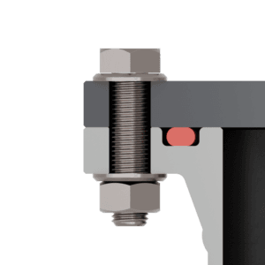
Designing the inside diameter (ID) of an O-ring correctly is mainly about ensuring the O-ring is slightly stretched for stability, but not overstressed, while still fitting the groove and mating hardware properly.
Here’s a practical engineering approach.
| Operating condition | Design location of the inside diameter | Recommended adjustment |
|---|---|---|
| Without pressure | On the inside diameter or in the middle of the groove | No specific adjustment necessary |
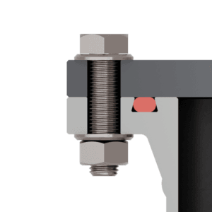
| System pressure from inside | On the outside diameter | 0-3% compression |
| System pressure from outside | On the inside diameter | 0-3% preload |
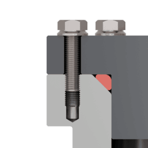
Designing a groove for a PTFE (Teflon) O-ring is quite different from elastomer O-rings (like NBR or FKM), because PTFE is rigid, non-elastic, and has very low friction but almost no recovery. That means the groove does not rely on “squeeze alone” — it must mechanically support and energize the seal correctly.
Below is a practical engineering layout approach.
| Aspect | Design guideline |
|---|---|
| Inside diameter | Keep the same as the groove inside diameter |
| Field of application | Preferably as a flange gasket |
| Groove filling | Almost 100% filling to avoid empty spaces |
| Special features of the material | Take into account the minimal stretchability and compressibility of PTFE |
These three factors—sealing gap (clearance), system pressure, and O-ring hardness (Shore A)—are tightly linked because together they determine whether the O-ring will seal properly or extrude and fail.
Think of it as a balance between:
- the force pushing the O-ring into the gap (pressure)
- the space it can be pushed into (sealing gap)
- the resistance of the material (hardness)
| System pressure | Sealing gap design | O-ring hardness | Measures against gap extrusion |
|---|---|---|---|
| Low | Larger sealing gap possible | Softer O-rings possible | Not absolutely necessary |
| Medium | Smaller sealing gap required | Medium to high hardness | Use of support rings on one side |
| High | Minimal sealing gap | High hardness preferred | Use of support rings on both sides |